Peltier Modules
Peltier Modules
Peltier coolers are thermoelectric refrigerators based on the Peltier effect — a phenomenon named after French watchmaker and amateur physicist Jean C. A. Peltier (1785–1845).
Peltier made his discovery almost 170 years ago, in 1834. The idea behind this phenomenon was revealed several years later, in 1838, by German physicist Heinrich F. E. Lenz (1804–1865). While experimenting with an electric current flowing through the junction of two dissimilar conductors, Lenz placed a drop of water into a small cavity at the junction of two bars made of bismuth (Bi) and antimony (Sb). When the electric current flowed in one direction, the drop of water froze. When the current flowed in the opposite direction, the frozen water melted. This experiment showed that when an electric current flows through the junction of two dissimilar conductors, that junction will either absorb or release heat, depending on the direction of the current flow. This phenomenon was named the Peltier effect.
This effect is the reverse of a discovery made in 1821 by German physicist Thomas J. Seebeck (1770–1831). This phenomenon takes place in a closed electric circuit consisting of dissimilar metals or semiconductors. If there is a temperature difference at the two junction points of dissimilar metals or semiconductors, voltage is induced in the circuit.
According to the well-known Joule's law, a conductor carrying a current generates heat proportional to the product of the resistance (R) of the conductor and the square of the current (I). Thus, Joule heat that evolves during a period of time (t) is calculated using the following formula:
| (Formula 11.1) |
In contrast to Joule heat, Peltier heat is proportional to the current, and the direction of heat transfer is reversed if the current is reversed. Experiments have shown that Peltier heat can be expressed by the following formula:
| (Formula 11.2) |
Here, q is the electric charge (q = I × t), and P is the so-called Peltier factor, the value of which depends both on the properties of the dissimilar materials carrying the current and on their temperatures.
Peltier heat is positive if it is released; otherwise, it is negative.
In the experiment conducted as shown in Fig. 11.1, the same Joule heat will be released in each calorimeter if both wires have the same resistance (Cu + Bi). This heat can be calculated using the following formula:
| (Formula 11.3) |
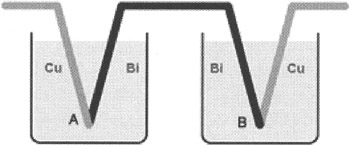
Figure 11.1: Arrangement for measuring Peltier heat (Cu — copper, Bi — bismuth)
Peltier heat, on the other hand, will be positive in one calorimeter and negative in the other. This experiment measured Peltier heat and derived the Peltier factor values for different pairs of conductors.
Note that the Peltier factor strongly depends on the temperature. Several Peltier factor values for different combinations of metals and alloys at different absolute temperatures (Kelvin scale, or °K) are provided in Table 11.1.
|
Fe - constantan |
Cu-Ni |
Pb - constantan |
|||
|---|---|---|---|---|---|
|
T(°K) |
P(mV) |
T(°K) |
P(mV) |
T(°K) |
P(mV) |
|
273 |
13.0 |
292 |
8.0 |
293 |
8.7 |
|
299 |
15.0 |
328 |
9.0 |
383 |
11.8 |
|
403 |
19.0 |
478 |
10.3 |
508 |
16.0 |
|
513 |
26.0 |
563 |
8.6 |
578 |
18.7 |
|
593 |
34.0 |
613 |
8.0 |
633 |
20.6 |
|
833 |
52.0 |
718 |
10.0 |
713 |
23.4 |
The Peltier factor, an important technical characteristic of materials, can be calculated using the Thomson coefficient, rather than having to be measured, as follows:
| (Formula 11.4) |
Here, P is the Peltier factor, α is the Thomson coefficient, and T is the absolute temperature.
This discovery had a huge effect on subsequent developments in physics and, later, in engineering.
The idea of the effect is this: When an electric current flows through the junction of two dissimilar materials, besides Joule heat (which always is produced), additional heat known as Peltier heat is either produced or absorbed, depending the direction of the current or of the temperature gradient. The degree to which this effect is manifested largely depends on the chosen conductors and the electric modes used.
A classic theory explains the Peltier effect. Electrons, moved by the current from one conductor to another, speed up or slow because of the internal potential difference at the junction point. In the first scenario, the kinetic energy of the electrons increases and is subsequently released as heat. In the second situation, the kinetic energy of the electrons decreases, and this energy loss is compensated by heat absorption. The second material, as a result, will cool.
The Peltier effect, like other thermoelectric phenomena, most strongly manifests itself in semiconductor circuits, composed of n- and p-type semiconductors.
Consider the thermoelectric processes that take place at the contact of such semiconductors. Suppose that the electric field direction causes electrons in the n-semiconductor and holes in p-semiconductor to move toward one another. After passing through the boundary, an electron enters the p-semiconductor zone and takes the place of a hole. This recombination releases heat (Fig. 11.2).
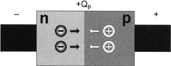
Figure 11.2: Release of Peltier heat at the contact of n- and p-type semiconductors
If the direction of the electric field is reversed, the electrons and holes will move in opposite directions. Holes moving from the boundary will increase in number because new pairs will be generated when electrons pass from the p-semiconductor to the n-semiconductor. The generation of such pairs consumes energy, and this energy loss is compensated by heat oscillations of the atomic lattice. Electrons and holes, generated as a result of appearing pairs, will be driven in opposite directions by the electric fields. Therefore, new pairs will continue to appear as long as there is a current through the contact. This will result in heat absorption (Fig. 11.3).
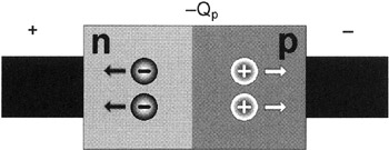
Figure 11.3: Absorption of Peltier heat at the contact of n- and p-type semiconductors
Thus, depending on the direction of the electric current through the contact of different types of semiconductors (p-n- and n-p-junctions), heat will be released or absorbed as electrons (n) and holes (p) interact and as new pairs of charges are recombined or generated. The usage of p- and n-semiconductors in thermoelectric refrigerators is illustrated in Fig. 11.4.
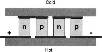
Figure 11.4: Using p- and n-semiconductors in thermoelectric refrigerators
Joining large numbers of n- and p-semiconductor junctions creates cooling elements — Peltier modules of significant capacity. The structure of a semiconductor Peltier module is shown in Fig. 11.5.
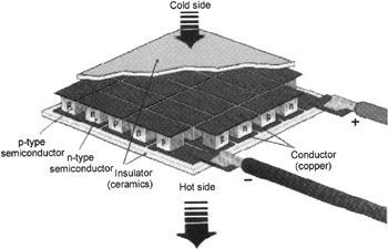
Figure 11.5: Structure of a Peltier module
The Peltier module is a thermoelectric refrigerator that consists of coupled p- and n-type semiconductors, which constitute p-n- and n-p-junctions. Each junction has heat contact with one of two heatsinks. If an electric current of a certain polarity passes through the junction, the temperature between the heatsinks in the Peltier module will drop: One heatsink will work as a refrigerator, and the other will generate and remove the heat. When the cold side of the Peltier module is joined to the surface of the object being protected, this module acts as a heat pump. This heat pump moves the heat from this object to the hot side of the module, which is cooled by air or water. Like any heat pump, it can be described by thermodynamic formulas. Therefore, Peltier modules can be called not only thermoelectric, but also thermodynamic modules.
Fig. 11.6 shows an external view of a typical Peltier module.
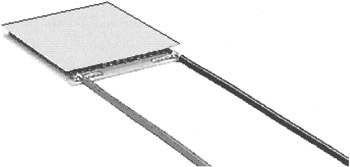
Figure 11.6: External view of a typical Peltier module
In a typical module, temperature can differ tens of degrees. If the hot side is cooled adequately, the other side will reach negative Celsius temperatures. To increase the temperature difference, it is possible to cascade properly cooled Peltier modules. This method provides a simple, reliable, and inexpensive way of obtaining a temperature difference that will cool electronic components efficiently.
Fig. 11.7 shows an example of cascaded Peltier modules.
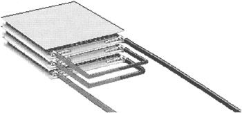
Figure 11.7: Cascaded Peltier modules
A cooling component based on Peltier modules is often called an active Peltier cooler, or simply a Peltier cooler.
Peltier modules make coolers more efficient than standard coolers based on the traditional heatsink-and-fan combination. In the process of designing and running coolers that use Peltier modules, you must keep in mind certain traits. These features are the results of the modules' construction, the principles of their operation, the architecture of the hardware of a modern computer, and the functional capabilities of the system and application software.
A key role is played by the power of the Peltier module, which generally depends on its size. A weak module will not be able to guarantee the necessary level of cooling, which may lead to overheating and failure of a cooled electronic element, such as a processor. However, using a Peltier module that is too powerful may lower the temperature of the cooling heatsink to such a level that the moisture in the air condenses — a dangerous situation for electronic circuits. Water constantly formed by condensation may cause the electronic circuits of the computer to short-circuit. This is the time to recall that the distance between lead wires in modern circuit boards is often only a fraction of a millimeter.
Nevertheless, powerful Peltier modules in high-performance coolers and additional cooling systems allowed KryoTech and AMD, in a combined research project, to overclock AMD processors created with traditional technology beyond 1 GHz. They almost doubled the operating frequency. However, the given performance level was reached under conditions that ensured the stability and reliability of the processors working in overclocked modes. The result of such experimental overclocking was a performance record among 80x86 processors.
KryoTech is famous for more than its experiments related to extreme processor overclocking. Its facilities for cryogenic freezing of computer components also have become widely known. They have been equipped with appropriate electronic components and employed as platforms for many high-performance servers and workstations. Meanwhile, AMD confirmed the high level of its products and received experimental materials for further improvement of the architecture of its processors. Similar research has been conducted with Intel Celeron, Pentium II, and Pentium III processors and has increased performance significantly.
Note that Peltier modules, in the process of operating, give off a relatively large amount of heat. For this reason, you should not only have a powerful fan for your cooler, but also a means of lowering the temperature of the inside of the computer's case to avoid overheating the rest of the components. To do this, you should use additional fans in the construction of the case.
An external view of an active cooler that uses semiconductor Peltier modules is presented in Fig. 11.8.
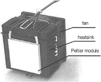
Figure 11.8: External view of a cooler with a Peltier module
Examples of Peltier modules manufactured in lots are Osterm products (http://www.osterm.ru). They are distinguished by their maximum consumed current (Imax, in amperes), their maximum voltage (Umax, in volts), cooling power (Qcmax, in watts), the maximum temperature drop (dTmax, in kelvins) between the hot and cold sides measured in a vacuum without a workload, and their dimensions.
Table 11.2 lists the working parameters for some Peltier modules manufactured in lots.
|
Serial number |
Imax (A) |
Umax (V) |
Qcmax (W) |
dTmax (°K) |
L × W × H (mm) |
|---|---|---|---|---|---|
|
K1-127-1/0.8 |
6.0 |
15.4 |
50.0 |
71 |
30 × 30 × 3.1 |
|
K1-241-1/0.8 |
6.0 |
29.2 |
95.0 |
71 |
40 × 40 × 3.1 |
|
K1-127-1/1.3 |
3.9 |
15.4 |
33.4 |
73 |
30 × 30 × 3.6 |
|
K1-241-1/1.3 |
3.9 |
29.2 |
63.4 |
73 |
40 × 40 × 3.6 |
|
K1-127-1/1.5 |
3.0 |
15.4 |
27.0 |
73 |
30 × 30 × 3.8 |
|
K1-241-1/1.5 |
3.0 |
29.2 |
51.2 |
73 |
40 × 40 × 3.8 |
|
K1-71-1.4/1.1 |
8.5 |
8.6 |
41.9 |
71 |
30 × 30 × 3.8 |
|
K1-127-1.4/1.1 |
8.5 |
15.4 |
75.0 |
71 |
40 × 40 × 3.8 |
|
K1-71-1.4/1.5 |
6.0 |
8.6 |
30.0 |
73 |
30 × 30 × 3.9 |
|
K1-127-1.4/1.5 |
6.0 |
15.4 |
53.0 |
73 |
40 × 40 × 3.9 |
|
K1-127-2/1.5 |
13.0 |
15.5 |
120.0 |
73 |
55 × 55 × 4.6 |
Keep in mind that cooling systems based on Peltier modules are used not only in electronic systems, but also in computers. Similar modules are used to cool various high-precision devices. This primarily applies to experiment-based research in physics, chemistry, and biology.
Examples of several Peltier modules released by Osterm are shown in Figs. 11.9–11.13.
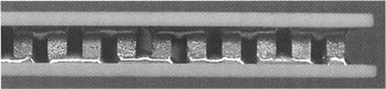
Figure 11.9: Semiconductors of p- and n-types in a Peltier module
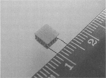
Figure 11.10: Tiny Peltier module
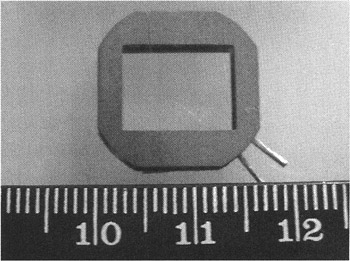
Figure 11.11: Shaped Peltier module
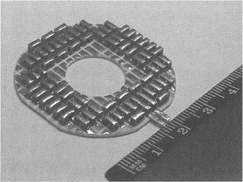
Figure 11.12: Peltier module with one ceramic platter removed
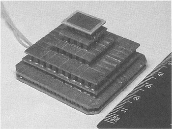
Figure 11.13: Cascaded Peltier module
Information on modules in Peltier coolers, including their features and the results of their usage, can be found on the Internet at Web addresses including:
-
http://www.tomshardware.com
-
http://rudteam.narod.ru/english/index.html
-
http://www.kryotech.com
-
http://www.melcor.com
-
http://www.supercool.se
-
http://www.computernerd.com
Features of Operation
Peltier modules, when used to cool electronic elements, have relatively high reliability. In contrast to refrigerators created using traditional technology, they do not have moving parts. To increase the efficiency of their operation, these modules can be cascaded. Cascading allows protected electronic components to cool below 0°C (32°F), even with significant power dissipation.
Besides the obvious advantages, Peltier modules have some specific properties that must be considered when using them in cooling equipment. Some of these properties have been mentioned, but to correctly use a Peltier module, you need to take a more detailed look at these characteristics. The following operating features are among the most important:
-
Peltier modules release a large amount of heat in the course of operation. They require in the cooler heatsinks and fans capable of efficiently deflecting surplus heat from the cooling modules. Thermoelectric modules are noted for their relatively low efficiency coefficient; when they act as heat pumps, they are powerful sources of heat. Using these modules in cooling devices, intended to protect the electronic components of the computer, dramatically increases the temperature within the system unit. This sometimes requires additional cooling devices within the computer case. If you don't use additional cooling, the high temperatures complicate operating conditions — even for the modules. Note that using Peltier modules creates a relatively heavy extra load for the power supply to handle. Including the values of currents required by Peltier modules, the power supply unit installed on the computer must be 250 W. Therefore, it makes sense to choose an ATX motherboard and case with a powerful power supply unit. Doing so will simplify the task of organizing optimum temperature conditions and electric modes for the components of the computer.
-
If a Peltier module fails, the cooled element is isolated from the heatsink of the cooler. This leads to a speedy breakdown of the stable temperature conditions of the element, quickly followed by a breakdown of the element itself from overheating. Because of this, it is wise to choose high-quality modules from well-known brands. Such modules are characterized by high reliability. Their mean time between failures (MTBF) often exceeds 1 million hours.
-
The low temperatures produced by the operation of Peltier coolers can be too powerful and cause moisture from the air to condense. This is dangerous for electric components; water can short-circuit elements. To avoid such a danger, choose a Peltier cooler with the optimal power for your needs. Condensation depends on a few parameters; the most important are the temperature of the surrounding area (the air inside the case), the temperature of the object being cooled, and the humidity of the air. The warmer and the more humid the air inside the case, the greater the likelihood of condensation, and, thus, the greater chance that electronic elements of the computer will break down. Table 11.3 illustrates how the temperature at which moisture will condense depends on the amount of moisture in the air and the air temperature. Using this table, you can easily figure out whether or not there is a danger of condensation. For example, if the temperature inside the case is 25°C (77°F), and the humidity is 65%, then condensation of moisture on the cooled object will occur when its surface temperature drops below 18°C (64°F).
Table 11.3: Temperatures at Which Moisture Will Condense Temperature (°C)
Humidity (%)
30
35
40
45
50
55
60
65
70
75
80
85
90
95
30
10.5
12.9
14.9
16.8
18.4
20.0
21.4
22.7
23.9
25.1
26.2
27.2
28.2
29.1
29
9.7
12.0
14.0
15.9
17.5
19.0
20.4
21.7
23.0
24.1
25.2
26.2
27.2
28.1
28
8.8
11.1
13.1
15.0
16.6
18.1
19.5
20.8
22.0
23.2
24.2
25.2
26.2
27.1
27
8.0
10.2
12.2
14.1
15.7
17.2
18.6
19.9
21.1
22.2
23.3
24.3
25.2
26.1
26
7.1
9.4
11.4
13.2
14.8
16.3
17.6
18.9
20.1
21.2
22.3
23.3
24.2
25.1
25
6.2
8.5
10.5
12.2
13.9
15.3
16.7
18.0
19.1
20.3
21.3
22.3
23.2
24.1
24
5.4
7.6
9.6
11.3
12.9
14.4
15.8
17.0
18.2
19.3
20.3
21.3
22.3
23.1
23
4.5
6.7
8.7
10.4
12.0
13.5
14.8
16.1
17.2
18.3
19.4
20.3
21.3
22.2
22
3.6
5.9
7.8
9.5
11.1
12.5
13.9
15.1
16.3
17.4
18.4
19.4
20.3
21.2
21
2.8
5.0
6.9
8.6
10.2
11.6
12.9
14.2
15,3
16.4
17.4
18.4
19.3
20.2
20
1.9
4.1
6.0
7.7
9.3
10.7
12.0
13.2
14.4
15.4
16.4
17.4
18.3
19.2
19
1.0
3.2
5.1
6.8
8.3
9.8
11.1
12.3
13.4
14.5
15.5
16.4
17.3
18.2
18
0.2
2.3
4.2
5.9
7.4
8.8
10.1
11.3
12.5
13.5
14.5
15.4
16.3
17,2
17
-0.6
1.4
3.3
5.0
6.5
7.9
9.2
10.4
11.5
12.5
13.5
14.5
15.3
16.2
16
-1.4
0.5
2.4
4.1
5.6
7.0
8.2
9.4
10.5
11.6
12.6
13.5
14.4
15.2
15
-2.2
-0.3
1.5
3.2
4.7
6.1
7.3
8.5
9.6
10.6
11.6
12.5
13.4
14.2
14
-2.9
-1.0
0.6
2.3
3.7
5.1
6.4
7.5
8.6
9.6
10.6
11.5
12.4
13.2
13
-3.7
-1.9
-0.1
1.3
2.8
4.2
5.5
6.6
7.7
8.7
9.6
10.5
11.4
12.2
12
-4.5
-2.6
-1.0
0.4
1.9
3.2
4.5
5.7
6.7
7.7
8.7
9.6
10.4
11.2
11
-5.2
-3.4
-1.8
-0.4
1.0
2.3
3.5
4.7
5.8
6.7
7.7
8.6
9.4
10.2
10
-6.0
-4.2
-2.6
-1.2
0.1
1.4
2.6
3.7
4.8
5.8
6.7
7.6
8.4
9.2
Besides the features already mentioned, you must consider situations that use thermoelectric Peltier modules to cool high-performance CPUs in powerful computers.
The efficiency of Peltier module usage depends on the model and its operating modes. Choosing a nonoptimal model and setting incorrect operating modes can lead to dangerous situations, because such choices do not ensure the required operating conditions for the cooled components. They can even result in the failure of the components to be protected. The optimal choice of a Peltier module is not a trivial task.
Fig. 11.14 illustrates one of the calculation methods used to select a Peltier modules. (This graph is published with the permission of Osterm.) The graph shows the thermoelectric characteristics of a Peltier modules manufactured in lots. The measurements are as follows:
-
Th (Th) — Temperature of the hot side of the Peltier module (in kelvins)
-
Imax (I) — Maximum allowed current (in amperes)
-
dTmax (dT) — Maximum temperature difference between the hot and cold sides of the Peltier module, measured in a vacuum without a workload (in kelvins)
-
Umax (U) — Maximum allowed voltage (in volts)
-
Qcmax (Qc) — Maximum cooling power (in watts)
-
RdTm — Module resistance to the alternate current (in ohms)
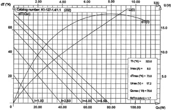
Figure 11.14: Thermoelectric characteristics of a Peltier module
The values of these parameters of the Peltier module depend on the temperature of its hot side. They are different from the values specified in documentation, where all characteristics are provided for a temperature of 300°K (27°C).
Performing calculations based on this graph implies the following:
-
Using the U(I) graph, for the selected U voltage, determine the I current that flows through the Peltier module. The value of the I current must fit within the range of the ascending part of the dT(I) curve.
-
For the value of the I current, choose characteristic using the curves that determine the dependence of dT on Qc (in the lower left part of the graph).
-
With the known values of Th and dT, determine the temperature of the cold side of the Peltier module (Tc), calculated according to the following formula:
(Formula 11.5) 
Here, Tc is the temperature of the cold side of the module, Th is the temperature of the hot side of the module, and dT is the temperature difference.
From the graphs of the functions illustrating the dependence of dT on Qc, it is obvious that as the thermal power (Qc) of the cooled element increases, the temperature drop between the hot (Th) and cold (Tc) sides of the Peltier module decreases. (See Formula 11.5.) At the same time, the higher the current flowing through the module (defined by the U voltage), the greater the dT difference, provided that the Qc thermal power is fixed.
The following example illustrates the calculation required to choose a Peltier module. It is based on the following initial conditions: The supplied voltage is 12 V; the thermal powers of the element to be cooled are 20 W, 40 W, and 60 W; and the temperature of the hot side of the Peltier module (equal to the temperature of the base of the heatsink installed on the Peltier module) is 50°C. The calculation produces the following:
-
For a voltage of 12 V, the current is 5 A.
-
For a current of 5 A and a thermal power of the cooled element equal to 20 W, the temperature difference (dT) is approximately 45°K (45°C). At 40 W, it is 25°K (25°C), and at 60 W, it is 4°K (4°C).
-
Given the values of temperature difference (dT) and of the temperature of the hot side of the Peltier module, which is 323°K (50°C) in this example, it is possible to calculate the Tc temperature for each Qc value. When the thermal power of the cooled element is 20 W, the temperature of the cold side of the Peltier module is 278°K (5°C). At 40 W, it is 298°K (25°C), and at 60 W, it is 319°K (46°C).
If a more powerful Peltier module is used, it is possible to achieve a greater temperature difference between the hot and cold sides. For example, a module with a Qc of 131 W, an I of 8.5 A, and a U of 28.8 V will ensures a temperature difference of 308°K (35°C) to 313°K (40°C) for objects with a thermal power equal to 60 W.
When choosing an appropriate module based on cooling power, keep in mind the module's thermal power. For example, when the module under consideration operates in the chosen modes (U = 12 and I = 5), this power is 60 W. There also is the thermal power of the element being cooled. The heat flux generated by these sources is a heavy burden for a cooling system.
Correctly chosen and appropriately run Peltier modules are efficient cooling devices that ensure a temperature for the case of the cooled element below the ambient temperature.
Cooling devices normally composed of a heatsink and a fan must not only dissipate rather powerful heat flux, they also must ensure a low temperature on the hot side of the Peltier module. The module ensures the temperature difference between its hot and cold sides; therefore, the lower the temperature supported on its hot side, the lower the temperature of its cold side. (See Formula 11.5.)
If traditional cooling devices can't ensure the required parameters, one possible solution is a water cooling system. Again, the temperature of the cold side of the Peltier module, and, consequently, that of the adjoining surface of the cooled element, depends both on the temperature difference and on the value of the temperature on the hot side of the Peltier module.
When choosing a Peltier module of appropriate cooling power, it is necessary to ensure that the entire surfaces of its cold and hot sides are used. Otherwise, the parts of the module that do not have contact with the surface of the protected object (such as a processor chip) will only waste power and emit heat, decreasing overall cooling efficiency (Fig. 11.


