Chapter 2: Data Networking Technologies
Chapter 2: Data Networking Technologies
Before we enter the terminology and acronyms jungle that normally characterizes any telecommunications or data networking book, we need some tools to help us easily find the way out of the thickest parts of it and avoid becoming lost halfway through. This chapter equips you with a fundamental grasp of data networking technology required to understand the topics in this book. In the first section we introduce tunneling and labeling technologies that are fundamental to the provision of Virtual Private Networks over a shared internetworking infrastructure, as well as mobility support. We have chosen to handle IP security fundamentals in this section, since security is tightly coupled with tunneling technologies in VPN provisioning, and in fact one of the IP Security (IPSec) options (IPSec tunnel mode) is a tunneling mechanism frequently used in IP VPN service provisioning. In the second section we discuss quality of service (QoS) issues related to the provisioning of VPN services. This then takes us to the following section, which helps in understanding the importance of authentication, authorization, and accounting (AAA) to implement access control, a fundamental prerequisite for the ability to meet service levels and to charge for services. In the fourth section we address the necessity of network services to facilitate network operation and service provisioning.
After we complete this brief data networking tutorial, the next two chapters introduce the relevant aspects of cellular and Wireless LAN systems technology. Note that most of the topics in this chapter warrant their own book, and we will only scratch the surface. However, we will try to always reference standard documents and other worthwhile material for those interested in probing further.
Tunneling and Labeling Technologies
Mobile VPN requires using technologies that leverage publicly available infrastructure, operated by service providers, that allows for "virtually private" connectivity between customer network sites and the mobile stations logically belonging to them, known as Mobile VPN members or subscribers. Such technologies (covered in depth in Chapter 5) are based on the encapsulation of the customer network data (also known as user data) packets into other packets, delivered using the networking technology of the shared network. This allows the use of the addressing scheme and the technology of the shared network, while delivering customer data belonging to networks that may be using different addressing schemes and different network or link layer protocols.
This encapsulation, or tunneling, as it is more often referred to in the data networking world, not only provides the ability to deliver data to and from mobile stations, but sometimes also adds integrity and confidentiality protection. Also, when the operator wants to support QoS, these technologies facilitate the delivery of predictable network transit, for instance, via traffic-engineered paths identified by a sequence of labels, like in Multi-Protocol Label Switching (MPLS). MPLS also provides the means to maintain the connectivity among multiple sites of a customer network in a fairly automatic way (like BGPv4/MPLS-based VPNs; [RFC2547]). Again, these topics are covered in greater depth in Chapter 5.
Sometimes the services offered by a carrier may simply be the forwarding of data from a wireless access gateway to the customer network site via a tunnel or a fixed access line. (See Chapters 6 and 7 for the definition of the wireless gateway entities in 3GPP- and 3GPP2-compliant systems.) Other times the service may extend to a managed multiple-sites VPN service, where the wireless access gateway becomes simply one of the customer network sites. Tunnels are also used to support mobility, by keeping one endpoint fixed and having the other "follow" the mobile data node at its point of attachment to the network (where normally the link layer of the access network is terminated). Mobile IP and GPRS Tunneling Protocol (GTP), covered in this chapter, are good examples of the latter.
The data may be transferred at the network layer or at the link layer using a protocol such as Point-to-Point Protocol (PPP). In this case, the wireless network simply terminates the wireless access protocols and relays the PPP or other link layer protocol to a network access server in the customer network. This is pretty much always the case with circuit-switched data-based MVPNs, but it can also be frequently encountered in packet-based wireless data services, where it might be favored because of the wide use of PPP-based remote access by enterprises on wireline access media. The approach involving PPP is normally based on a tunneling protocol called L2TP.
Layer Two Tunneling Protocol
Layer Two Tunneling Protocol (L2TP) is defined in [RFC2661] as an IETF protocol that provides a standard approach to the tunneling of PPP frames over IP. Cisco and Microsoft had originally developed proprietary ways to accomplish this (via Layer Two Forwarding, or L2F, and Point-to-Point Tunneling Protocol, or PPTP, respectively), but the industry recognized the need for a standard-based approach. As a result, the IETF PPP Extensions (PPPEXT) Working Group was chartered with the task to define such a standard. The outcome was a tunneling protocol that could potentially be transported on any cell, frame, or packet-based transport network. In particular, the widely used UDP/IP transport was chosen as the preferred protocol (UDP stands for User Datagram Protocol).
L2TP defines two network entities with two distinct roles to be the peers for this protocol:
-
The L2TP Access Concentrator (LAC) is located at the point of termination of access network protocol, and it can establish tunnels toward appropriate L2TP network access servers (LNSs).
-
The LNS terminates tunnels from LACs and also offers network access services such as user authentication and address assignment.
An LAC client running on a laptop or any other suitable computing device could also be used to initiate L2TP tunnels toward LNS. The LAC client-based usage of L2TP constitutes a technology-independent way to access remote networks, provided that these are reachable at the network layer. Figure 2.1 illustrates the model we have just discussed.
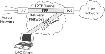 Figure 2.1: The L2TP model.
L2TP defines a reliable control channel. Over this control channel it is possible to establish a tunnel between the LAC and the LNS. The tunnel establishment phase normally includes authentication via the L2TP exchange of a secret between the LAC and LNS (in the form L2TP tunnel; password). The authentication of the party attempting to set up a tunnel is important, since it is not desirable to have an LNS accept any L2TP commands coming from an unknown LAC if they are not authorized to do so. However, since the L2TP protocol does not come with data origin authentication and confidentiality, L2TP cannot be considered a secure protocol. In fact, it is still possible for an attacker to send packets to an LNS or an LAC and impersonate each node's peer. Securing L2TP requires another IETF protocol suite defined for the support of IP security: IPSec. We provide details on IPSec and IPSec modes later in the chapter, adding more information and explaining how to secure L2TP tunnels.
When a tunnel is established between the LAC and LNS, it is possible to set up and tear down a PPP session and to forward associated frames between the two nodes using the L2TP encapsulation format over the L2TP data channel. The L2TP header (see Figure 2.2) includes the Tunnel ID and the Session ID information to enable two levels of multiplexing. The Tunnel ID defines a tunnel between two peers, and it therefore implicitly identifies the peer node at the receiving end. The Session ID identifies the particular PPP session within the tunnel. Because the Session ID information can be exchanged only after the tunnel between the LAC and LNS is in place, PPP call setup latency could be reduced if the L2TP tunnel is already set up when a PPP session needs to be handled. Often carrier-class deployments establish L2TP tunnels up front.
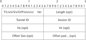
Figure 2.2: The L2TP message header.
User authentication within PPP sessions normally takes place transparently to the LAC. The LAC merely decides to which LNS the L2TP session has to be set up and subsequently forwards the incoming PPP frames to it. The selection of the LNS can be based on information such as the destination number called, or when used in GPRS network, on the identifier of the network the PPP user is requesting access to. Forwarding PPP frames to the correct LNS lets the PPP authentication phase occur between the LNS and the PPP client on the remote device. The LAC can also perform proxy authentication by collecting authentication data from the incoming call and relaying it to the LNS using L2TP signaling. This requires mutual trust relationships to be established between the LAC and LNS operators. The LNS, after it has received the proxy authentication data from the LAC, may later optionally reauthenticate the user at the PPP level by initiating a new PPP authentication phase before moving to the configuration of the network layer.
The LAC may determine the LNS IP address dynamically based on the received username and password, which may contain the Network Access Identifier (NAI), defined in [RFC2486]. The LAC can in this case conduct a first pass of user authentication with the AAA infrastructure (see the "Authentication, Authorization, and Accounting" section later on page 63). The AAA infrastructure determines the user Home AAA server based on the NAI domain component. The AAA infrastructure could return, when the user is granted access, L2TP tunnel information such as the LNS IP address and the L2TP password. In fact, the LAC may decide whether the user requires an L2TP tunnel to an LNS or simply access to a network directly attached based on the domain component of the username (formatted like this: domain\user). In this way, it works like a regular network access server (NAS). For instance, user JDoe, may want to access the Internet using the username Inet-access\JDoe, and the corporate network using L2TP via the username Corpnet-access\JDoe. L2TP can handle both calls coming from the access network to the LAC, denominated "incoming calls," as well as requests from the LNS to call a specific terminal on the access network (to implement, for example, a call-back service), denominated "outgoing calls."
Given its flexibility and its rich set of options, L2TP has become widely used to "divorce" the location of access termination from the location of termination of the PPP protocol, with large deployments in global remote access facilities for large corporations (see Chapter 5). It became a de facto standard for services such as remote access outsourcing when an enterprise relies on a service provider to handle their remote worker's PPP sessions at their facilities (POPs equipped with remote access servers) and then relay them to corporate data center for authentication and IP address assignment. Given current L2TP popularity with corporations, it is not surprising that both the GPRS/UMTS and CDMA2000 standards allow for its use as a way to support compulsory access to corporate networks (more on this in Chapters 6 and 7), thus providing an easy way to integrate wireless and wireline access methods. Further information on L2TP can be obtained from [Black2000].
IP in IP Tunneling
IP in IP, also referred to as IPIP, is the most basic tunneling service; it encapsulates an IP packet into another IP packet. This encapsulation method is specified in [RFC2003], which has been developed as a companion document to [RFC2002] (the original Mobile IPv4 specification). In IPIP the outer IP packet header identifies the addresses of the tunnel endpoints, where the source address is the address of the encapsulator and the destination address is the address of the decapsulator.
In recognition of the fact that sometimes encapsulating an IP packet in another IP packet may lead to excessive overhead, especially when small payload IP packets are tunneled, it was necessary to define a way to compress the information associated with the inner IP packet header. [RFC2004] describes the minimal IP in IP encapsulation that defines an encapsulation header inserted between the outer IP packet and the inner packet payload so that the decapsulator can reconstruct the inner IP packet header (see Figure 2.3). This can lead to 8 to 12 bytes of saving per packet.
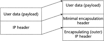
Figure 2.3: The minimal encapsulation for IP.
| Note |
Both IP in IP and minimal encapsulation for IP tunneling protocols rely on other protocols (e.g., Mobile IP) or network element provisioning to get the tunnel set up. Also, IP in IP by itself is not secure and requires IPSec for this function. This combination is normally referred to as IPSec tunnel mode. |
GRE Protocol
The Generic Routing Encapsulation (GRE), specified in [RFC2784], is an IETF standard defining multi-protocol encapsulation format that could be suitable to tunnel any network layer protocol over any network layer protocol. This concept was originally specified in [RFC 1701], which was an informational RFC. When this original protocol was moved to a standards track, the decision was made to replace it with two separate RFCs: [RFC2784] and [RFC2890]. [RFC2890] is an extension of the basic GRE header described in [RFC2784]. It was determined necessary because [RFC 2784] does not lend itself to encapsulation of PPP frames, since it does not have a sequence number in the GRE encapsulation format. This limitation was removed by adding a sequence number extension to the basic GRE header. Also, [RFC2784] does not allow for multiplexing onto the same GRE tunnel of tunneled packets belonging to different administrative entities possibly adopting overlapping private address spaces (a very useful feature for the provision of Virtual Private Networks). This limitation was also removed by adding a key field—that is, a numeric value used to uniquely identify a logically correlated flow of packets within the GRE tunnel—as an extension of the basic GRE header. These extensions to a basic GRE defined by [RFC2890] were especially useful in wireless data communications. For example, they allowed for in-sequence delivery of PPP frames over the R-P interface in CDMA2000 (see Chapters 4 and 7 for more details), and the provisioning of compulsory MVPN services.
GRE, as defined by these RFCs, is normally used in two classes of applications: the transport of different protocols between IP networks and the provision of VPN services for networks configured with potentially overlapping private address space. The GRE header key field can be used to discriminate the identity of the customer network where encapsulated packets originate. In this way, it provides a way to offer many virtual interfaces to customer networks on a single GRE tunnel endpoint. This feature allows for policy-based routing (that is, when routing decisions are not based only on the destination IP address but on the combination of a virtual interface identifier, and the destination IP address) and relatively easy per-user network accounting. Also, a GRE header allows the identification of the type of the protocol that is being carried over the GRE tunnel, thus allowing IP networks to serve as a bearer service onto which a virtual multi-protocol network can be defined and implemented.
| Note |
Similar to the IP in IP tunneling mechanism, the GRE tunneling technology does not include a tunnel setup protocol. It requires other protocols, such as Mobile IP, or network management to set up the tunnels. It also does not include security mechanisms and must be combined with IPSec to support secure user data delivery. |
Mobile IP
Mobile IP can be based on a variety of tunneling mechanisms, but by itself, it does not provide one. As we mentioned in the "IP in IP Tunneling" section, Mobile IP was originally defined by [RFC2002], which later was made obsolete by the more up-to-date [RFC3220] to support host mobility at the network layer (IP). Mobile IP was originally conceived to let nodes with fixed static IP addresses to be permanently reachable even if they changed their point of attachment to the network. Its applicability was limited to supporting the mobility of Internet hosts and routers only in certain environments, such as campus or university networks, or for defense applications. There was no support for dynamic address assignment and no accounting and user authentication features. However, Mobile IP was later adopted by cellular systems such as Motorola IDEN deployed by Nextel (a United States based operator) and more recently by CDMA2000 standard for core networks, and for these systems, it evolved to take into account the needs of commercial environments. Today Mobile IP is being increasingly considered a preferred method for support of multi-access technologies and inter-system roaming [Solomon1998].
Mobile IP is defined as a technology-independent tunnel setup and maintenance protocol used to allow roaming Internet hosts or routers to maintain constant IP address and uninterrupted IP-level connectivity back to a home network while changing points of attachment to a network and the network access technology.
| Note |
Throughout the book, we will interchangeably use the terms mobile node (MN) in accordance with Mobile IP and IETF terminology, or mobile station (MS) in accordance with 3GPP terminology. |
Implementing Mobile IP
Like L2TP, Mobile IP provides an architectural model that defines the roles of different entities that may be involved in Mobile IP operation. Mobile IP must be implemented in three main functions:
-
Home Agent (HA)
-
Foreign Agent (FA)
-
Mobile Node (MN)
HA and FA support the Mobile IP protocol on the mobile node's home and foreign (visited), networks respectively.
During the mobile IP communication session the HA is being continuously informed by the MN of its current location via Mobile IP Registration Request messages, as the MN roams through different networks. The HA and FAs available in Foreign Networks advertise their availability by means of agent advertisement messages broadcasted over the links directly attached to them. The location of the MN is represented by its care-of address (CoA) being temporarily assigned to it by the FA (or acquired by the MN itself in the visited network when Mobile IP operates in collocated care-of address mode). The HA forwards the traffic to MN (almost always through a FA) and accepts it from MN (possibly via FA) when reverse tunneling is used (see next paragraph). It also processes FA registration requests and manages Mobile IP tunnels for users gaining network access via the HA itself. The typical Mobile IP network model is shown in Figure 2.4.
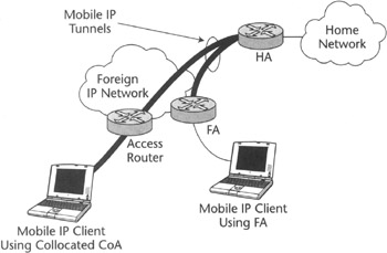
Figure 2.4: Mobile IP model.
The FA may forward packets from the MN directly to the Internet or tunnel them back to the HA in what is called Mobile IP reverse tunneling. Reverse tunneling is often necessary to avoid ingress filtering to drop packets from the MN, as well as to let corporations and network access providers operating the HA create VPNs in which all the traffic to and from the MN can be optionally secured and would always traverse the HA in its private network for tighter control and security. The standards also allow the MN to directly register with the HA when FA is not available, after it acquires an IP care-of address in the visited network, which in this case is called a collocated care-of address. This address would then be used by the MN to exchange Mobile IP registration messages and to tunnel packets to and from the HA, all without the need of an FA. Interestingly, this last feature did not find its way into the Telecommunications Industries Association (TIA) specification for CDMA2000, partially under the influence of wireless operators who would potentially lose control over the mobile users, since the mobile users could at will bypass the operator-owned FAs if this option were implemented.
An MN can be assigned a static IP address or it can obtain it dynamically from an IP address pool belonging to networks served by the HA. The FA, being a router in the visited network, is capable of serving visitor MNs. As depicted in Figure 2.5, the FA advertises its presence via periodical Mobile IP agent advertisements, or by responding with Mobile IP agent advertisements to Mobile IP agent solicitation messages sent by MNs visiting one of the networks served by the FA. When an MN moves to a network controlled by a certain FA, it can send a Mobile IP registration request (RRQ) to the FA, which in turn registers the MN with its HA by sending an RRQ to the appropriate HA. The HA may accept this RRQ (after authenticating the sender) and issue a Mobile IP registration response (RRP) to the FA, which in turn relays it to the MN. After this message exchange and all authentication phases are complete, the HA creates the IPIP or GRE tunnels to the FA and then start forwarding packets destined to a registered MN to the FA, which then relays them to the MN.
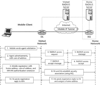
Figure 2.5: Typical Mobile IP registration procedure.
The Mobile IP protocol itself has undergone many changes and additions over the last decade, often referred to as extensions, to make it suitable for commercial deployment in various systems, especially because of the requirements of TIA specified in IS835, which defines Mobile IP as a basis for network layer user data mobility in CDMA2000. [1] For instance, replay protection has been added to the Mobile IP registration messages by the use of a Challenge-Response extension. Also, roaming support via the NAI extension (see later in the chapter for a description of NAI-based roaming) and dynamic home address assignment were added.
Dynamic home address assignment is an important Mobile IP feature which deserves a little more attention. Originally, Mobile IP was based on the assumption that all HAs in the network were statically allocated. This model, however, is less suitable for commercial wide-area deployment because it exposes service providers to extremely inefficient use of IP addresses. This model also makes HA a single point of failure, because once the HA serving a particular MN fails, the MN is denied the data services until this particular HA is back in service. Along with addressing these problems, dynamic HA allocation would provide more optimal routing and better utilization of landline data infrastructure when a MN is at a significant distance from its home network. This is why the second release of IS835 standards will include the ability to dynamically allocate the HA. More information on this topic as well as the examples of commercial Mobile IP deployment within CDMA2000 system framework can be found in Chapters 4 and 7.
The standards are also currently working on the definition of the so-called optimal routing. In this definition, the MN may update the node involved in a session, named the correspondent node (CN), of the IP address it has acquired in the visited network (the collocated CoA or the FA-generated CoA). Then the CN would be requested to send packets directly to this IP address. Optimal routing, however, proved not to scale well in a secure way, since the burden for correspondent nodes of millions of mobile nodes (such as Web servers) would be quite substantial. Other operational aspects of optimal routing are also not yet clear, which makes this a mode of operation with many open issues and question marks.
In contrast to IPv4, Mobile IP for IPv6 was strongly based on optimal routing and was expected to be supported by any IPV6-compliant host or router. This proposition, however, is currently encountering stumbling blocks in its standardization process because of security concerns about its reliance on trust in extension header processing and nonscalability with regard to security. Therefore, Mobile IPv6 deployment cannot be expected in its current shape until changes are provided and ratified by Mobile IP WG to make it deployable.
GPRS Tunneling Protocol
GPRS Tunneling Protocol (GTP) as originally defined in [3GPP TS 29.060] and [GSM TS 09.60], is a protocol used to support mobility of GPRS and UMTS mobile stations (MSs) roaming among geographical locations served by different Serving GPRS Support Nodes (SGSNs). The MS home network is represented by Gateway GPRS Support Nodes (GGSNs). GGSNs connected to SGSNs via GTP. As opposed to Mobile IP, GTP does not have to be supported in the MS. It is a protocol used only within the network, and the GTP protocol interworks with other protocols in order to interact with the MS and thus allow for tracking of its current whereabouts. In this section we do not present the details of the application of GTP in the GPRS and UMTS systems, since we discuss this extensively in Chapters 4 and 6. Instead, we focus on the description of the protocol and its technical details.
There are two versions of the GTP protocol. Version 0, described in [GSM TS 09.60], is used in the systems based on the GSM Base Station Subsystem (BSS) and applies to GSM Release 97 and 98. Version 1 is described in [3GPP TS 29.060] and applies to systems based on both GSM and UMTS radio access networks. 3GPP decided to create a new version of GTP protocol—not backward-compatible with GTPv0—because the group members wanted to introduce new features that could not be supported using the older version of the GTP protocol. They wanted to enable the separation of the protocol in a user plane protocol (GTP-U) and a control plane protocol (GTP-C). The reason for this split was dictated by the need to support GTP-U-based tunneling of user data over the interface between the UMTS core and the UMTS radio access network (Iu interface), without the need to use GTP-C to set up Iu tunnels. Another significant feature that differentiates GTPv1 from v0 is the support of multiple QoS levels per IP address assigned to an MS, which requires the establishment of multiple UMTS bearers and the use of multiple tunnels per MS data session. This led to the need of a multiplexing field in the GTPv1 header (the Tunnel Endpoint Identifier), which was then also used to replace a quite cumbersome and complex structure of the fields identifying a data session in GTPv0. Figure 2.6 illustrates the difference between GTPv0 and v1 header structure.
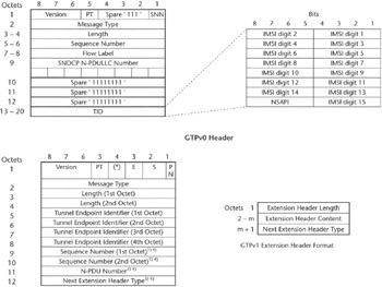
Figure 2.6: GTPv0 and GTPv1 headers.
GTPv0 could be transported over TCP or UDP. TCP was supposed to be used to offer reliable transfer of user data, which would be required for the transport of X.25 data. The wireless data networking market, though, by abandoning X.25 option has evolved in a way that made the use of TCP as a transport protocol for GTP redundant, and starting from UMTS R'99, GTP will be transported only over UDP. The UDP port number for GTPv0 is 3386, and the port numbers for GTPv1 are 2023 for GTP-C and 2052 for GTP-U.
GTP-C messaging includes the following:
-
Tunnel management messages used to detect fault conditions, loss of connectivity, and peer node restart.
-
Session management messages used to set up tunnels between GGSNs and SGSNs, and to update the per-node changes in the tunnel parameters such as QoS, new user plane, and control plane IP addresses of the new SGSN the MS has moved to.
-
Location management messages used to implement network-initiated GTP session setup procedures.
-
Mobility management messages used to transfer MS context and session context information at handoff time.
GTP-U is simply used to encapsulate user packets, but it can also monitor the transmission path for failures using tunnel management messages. It is used between SGSNs, between GGSNs and SGSNs, and between the UMTS SGSN and the UMTS RNC.
When a session is set up, GTP can transfer MS and subscriber-related data to the GGSN—using the "Protocol Configuration Options" Information Element (IE)—as well as some information on whether the subscriber has access rights, via subscription, to the access point (AP) network where the GTP tunnel is about to be created. This is performed via the Selection Mode IE, which transfers to the GGSN information on whether the AP was subscribed to by the user or just selected without subscription. This information is inserted into GTP by the SGSN. The IMSI (a globally unique identifier of the subscriber) and the MSISDN (the MS phone number) are sent by the SGSN to the GGSN using GTP-C, and the GGSN can relay this information to external servers, which, for instance, could apply user-identity-based policies. Also, GTP is used between SGSNs to transfer MS-related information at handoff time. It is also used when the MS attaches to an SGSN, and this new SGSN needs to retrieve subscriber identity information from the SGSN the MS was previously attached to before the MS last powered off (or, better, performed a detach procedure). More information on GPRS and UMTS mobility can be found in [Eberspacher2001] and [Kaaranen2001].
GTP can be used to encapsulate different user data protocols such as PPP, IPv4, and IPv6. Other protocols such as X.25 were originally allowed by the standard, but later the support for them was dropped by both vendor and operator communities along the standard evolution and maintenance path. It must be mentioned that GTP by itself is not secure and requires IPSec to add integrity protection and confidentiality. It does not require other protocols for GTP tunnel setup, however. GTP-U tunnels can be established by GTP-C or other protocols, such as Radio Access Network Application Part (RANAP) in UMTS.
Addressing Security
There is a common perception that IP is not a secure protocol and that the public Internet is exposed to all sorts of attacks from all sorts of individuals and groups, from the bored teenager who hacks Internet hosts to cyber-criminals using the Internet to damage institutions or break into banks. Indeed, this perception is correct. Being insecure is a recognized weakness of IP technology. Data integrity, data origin authentication, and confidentiality need to be provided either by:
-
Adding security mechanisms to the applications and devices using IP (examples include Web-based services such as e-commerce, e-banking, or access to corporate mail via Web interfaces).
-
Securing the IP protocol itself via some extensions and protocols defined by the IETF. These IP protocol extensions allow for an adequate level of security and are known under the umbrella name IPSec. IPSec is the name of the IETF Working Group that has developed an Internet security architecture [RFC2401] and the extensions to the IP protocol that this architecture has incorporated.
In this section, we describe both kinds of approaches—that is, network layer security provided via IPSec and application layer security provided by Transport Level Security (TLS, which recently superceded SSL). We also discuss security infrastructure enablers such as the Public Key Infrastructure (PKI), which supports the secure exchange of information and identity verification over the Internet. More information on both IPSec and PKI can also be obtained from multiple books such as [Doraswamy1999].
IPSec
The IPSec architecture defines the components necessary to provide secure communication between IP protocol peer entities, along with the related terminology. IPSec extends the IP protocol with two extension headers: the ESP header (the IP Encapsulating Security Payload, defined by [RFC2406] and the AH (Authentication Header, defined by [RFC2402]). The ESP is used to provide implicitly data confidentiality, payload integrity, and authentication, whereas AH is used to offer payload data integrity and guarantees the integrity of the nonmutable fields of the IP header as well. Both of these headers can be used either to encapsulate an IP packet in another IP packet (IPSec tunnel mode) or to encapsulate only the payload of an IP packet (IPSec transport mode). In Figure 2.7, AH is used to provide IPSec transport mode and ESP to provide IPSec transport mode, but a combination of AH and ESP is also possible, according to the standards.
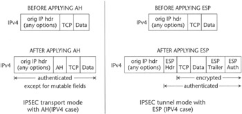
Figure 2.7: IPSec tunnel mode and transport mode with ESP and AH.
Although interoperable implementations of AH exist, in the VPN industry the ESP tunnel and transport modes are the most commonly used approaches. This is because the AH only provides the subset of ESP capabilities and because, by including in the authentication algorithm all the nonmutable IP header fields, the data origin authentication provided by AH can be offered by using IP tunnel mode with ESP. In fact, with the encryption service offered by the ESP tunnel mode, the inner IP packet, IP header, and payloads are implicitly protected from alteration along the route from tunnel ingress point to tunnel egress point. AH is nevertheless used by some protocols, such as Mobile IP, which require control messages to be protected via AH transport mode (and their encryption is optional). These security mechanisms, however, are general and are not forcing the use of a predefined encryption or authentication algorithm. Therefore, implementations can add encryption algorithms as they become available, without changing the architectural model. The most commonly used encryption protocol is Triple Data Encryption Standard (3DES), and the most commonly used authentication protocols are based on hash functions such as SHA-1 and MD-5. (SHA stands for Secure Hash Algorithm, MD for Message Digest.)
Fundamental components in the IPSec architecture are the Security Policy Database (SPD) and Security Association Database (SAD). Every IP interface for which IPSec is enabled must be equipped with a database of security classification rules and security actions. Each individual rule and action pair is known as a security policy. A security association (SA) defines a unidirectional packet treatment in terms of security policy enforcement actions that define which IPSec headers are applied, which encryption or authentication algorithms are used, and which keys are used to execute these algorithms. For each IP interface, there is a pair of such databases: one for the inbound traffic and one for the outbound traffic. If a packet does not match any rule, the interface may be configured to discard it.
To better understand these concepts, we can use the following example of an entry in an outbound IPSec SPD and SAD. A possible security policy can be defined by the following entry in the SPD of an IP interface:
"For all packets bound for destination IP address (192.43.56.82) and port number 8080, apply security association ALFA."
Security association ALFA is an entry in the SAD of the same IP interface, defined as based on IPSec tunnel mode with ESP and encryption algorithm 3DES and with an encryption key manually exchanged and provisioned at the endpoints. In the literature this SA is known as a symmetric key—based SA.
Security keys can be symmetric or asymmetric. Symmetric, or private, keys are distributed to both parties involved in a secure communication. Asymmetric keys are based on the RSA Data Security Inc. patented public keys cryptography paradigm, widely used in the industry to perform both encryption and authentication. In this setup, one party that wishes to engage in secure communications with others makes available a public key for retrieval at a well-known public keys repository. This approach is known as asymmetric key based because it uses a pair of keys: one that is public and widely distributed and another that is kept secret and never disclosed. Material encrypted using a public key can be decrypted only by using the associated private key. Conversely, only the public key can be used to decrypt material encrypted using the private key.
An asymmetric key system can be used to exchange a secret key necessary to run a symmetric-keys-based encryption algorithm. In other words, if a party knows the public key of an entity, it can send it a secret key, encrypted using the public key, and this party could unencrypt it using the private key and further use it for a symmetric-key-based encryption communication. To communicate with a peer using a public key, it is necessary to trust the source of this key. It is therefore necessary that the repositories of such information can be trusted (for instance, their public key is known and they digitally sign the public keys they hand out using their private key). These repositories are known as certificate authorities (CAs), and they form the base of the PKI. CAs and the PKI are discussed in greater detail in the next section.
An SA can be manually provisioned or dynamically managed, together with the security keys necessary to run the encryption or authentication protocols. This protocol is known as SA and Key Management Protocol, and the current IETF standard for this is known as Internet Key Exchange (IKE), [RFC2409]. Over time, IKE has undergone criticism of some of the engineering choices in its design. The IPSec Working Group in the IETF is currently mulling its evolution, and we can expect with some likelihood an IKEv2 at some time to come.
The IPSec protocol can be deployed in host-to-host, host-to-router, or router-to-router form. A router implementing IPSec and applying security policies to IP traffic is often referred to as an IPSec gateway. Figure 2.8 exemplifies the host-to-router and router-to-router cases, which are of special interest for VPN service provisioning.
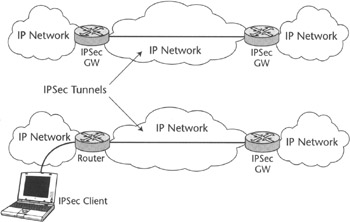
Figure 2.8: Sample IPSec architecture (gateways and hosts).
When IPSec is used for site-to-site IP VPNs (Virtual Private Networks built by connecting different sites of a corporate network using a shared IP-based infrastructure, see Chapter 5 for further details), IPSec tunnel mode is used. An example of IPSec transport mode application is L2TP tunnels integrity and confidentiality protection. It makes sense to use transport mode for L2TP tunnels protection because L2TP is a tunneling technology itself and the use of IPSec tunnel mode would result in redundant encapsulation, or nested tunnels. On the contrary, it makes much sense to use IPSec tunnel mode by itself for site-to-site VPNs, since packets need to be tunneled anyway and this mode provides both the tunneling and security required for this application.
Public Key Infrastructure
Public Key Infrastructure is an important security concept and needs to be carefully defined. Public keys, briefly described in the previous section and used in data networking to verify digital signatures, by themselves do not carry any information about entities providing the signatures. The data networking industry recognized this problem and adopted security certificates binding the public key and the identity of the key-issuing entity, which in turn can be verified using a trusted public key, perhaps known using a certificate issued by a higher hierarchical level authority. The certificates are issued and enforced by a certificate authority, which is authorized to provide such services to positively identified entities requesting them. To perform its functions, a CA must be trusted by all entities (PKI members) relying on its services.
A certificate contains the following information:
-
The certificate issuer's name
-
The entity for which the certificate is being issued (also known as the subject)
-
The public key of the subject
-
Time stamps (needed to determine the age of a certificate and its validity)
All certificates are signed using the CA's private key. A user of the certificate can verify that the certificate information is valid by unencrypting the signature and verifying it matches the digest of the content received in the certificate. The signature is normally an encrypted digest of the content—that is, a string of bits obtained by encrypting the result of some nonreversible elaboration of the content.
PKI members may agree on a standard lifetime of a certificate and thus determine when a certificate is stale or expired. Also, a certificate authority can publish a certificate revocation list (CRL), so that the PKI members can consult certificates no longer validated by the CA by checking them against the CRL.
The trust relationships between the CA and other PKI members must be established prior to any PKI transactions. Such relationships are usually outside the scope of PKI and for that matter outside the scope of networking technology. PKI trust relationships can be established on geographical, political, sociological, business, or ethnic basis and can span industries, countries, population groups, or other entities bound by common interests. The PKI trust models could in theory be based on a single CA, which would be used to create a worldwide PKI similar to the worldwide Internet or a hierarchy of distributed CAs (see Figure 2.9) in which every CA can be trusted by following a certificate chain to a common certificate authority the parties entering secure communication trust.
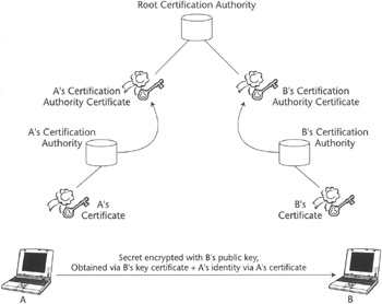
Figure 2.9: PKI based on distributed CA hierarchy.
In Figure 2.9 we describe the case of two parties, A and B, willing to exchange a secret. Party A retrieves B's public key from B's certificate. The certificate can be verified because it is signed with B's CA private key, and this can be checked by retrieving B's CA public key from B's CA certificate, which in turn can be verified by using the public key of a root certification authority that is guaranteed to be valid—for instance, because it is burned into the code of the PKI client on A's software module. Once B's public key is available, A encrypts the secret using it, and then it can send this encrypted message to B, along with its own (that is, A's) certificate and a digest of the encrypted secret, computed using A's private key. On reception of this message, B checks that the encrypted secret effectively comes from A by checking the digest using A's public key, retrieved from A's certificate, then it proceeds to decrypt the secret using B's private key.
The certificates can be issued in various formats. The de facto security standard widely accepted by the industry is [X509] defined by ITU. Public and private entities relying on services (that is, trusting) provided by a common CA and accept its certificates from the PKI. Members of PKI groups can easily identify themselves to one another based on certificates provided by the CA. For this purpose the members of the PKI only need to establish secure trust relationship with one member of the PKI, the certificate authority and not with the other members. So, in short, PKI can be defined as a virtual entity combining multiple physical entities by a set of policies and rules binding public keys to the identities of key-issuing entities via the use of a certificate authority.
Three main functions of PKI include:
-
Certification
-
Validation
-
Revocation
Certification, or binding a key to an identity by a signature, is performed by the CA, while validation, or more specifically, certificate authenticity verification, can be performed by any PKI entity. The process of certification includes the generation of public key pairs, including public and private keys, generated by the user and submitted to the CA as a part of the request, or generated by the CA on a user's behalf. Validation involves checking the signature issued by CA against the CRL and the CA public key. The revocation of an existing certificate before its expiration date is also performed by a CA. After the certificate is revoked, the CA updates the CRL with the new information. In a typical scenario, when the user needs to obtain or validate a certificate that has been presented, it issues a request to the CA. After the requested certificate is issued or its validity verified, the appropriate information is sent by the CA to a certificate repository, which also includes the CRL.
PKI is a relatively recent networking concept defined by IETF and ITU standards and drafts. It is now being rapidly adopted by the data networking industry with virtual private networking being no exception. Authentication and key management services provided by the PKI via the use of certificates are a perfect mechanism to support stringent VPN security requirements. To use these services, VPN clients and gateways must support PKI functionalities such as key generation, certificate requests, and common CA trust relationships.
SSL and TLS
Secure Sockets Layer (SSL) technology, originally developed by Netscape Communications Corporation, is increasingly viewed as an inexpensive and easy way to provide services similar to that provided by IP VPNs when the need to secure the IP communication between pairs of hosts is only occasional, application-dependent, or when extra level of security is required to protect the applications exchanging data. The reason is simple: SSL is usually included in commercial Internet browsers and does not require any additional software on the client side and almost no end-user involvement in the establishment of a secure connection. In recent years SSL became very popular for e-commerce applications and online banking and trading to support secure transactions requiring little user participation. For these reasons we decided to include a section describing SSL functionalities and comparing it with IPSec.
| Note |
We must emphasize that in strict terms SSL technology has no relationship to virtual private networking. SSL can be used to achieve results similar to VPN in some cases and has therefore often been mistakenly referred to as a type of VPN or a possible near future replacement for VPN by many in the data networking community. |
SSL technology is implemented in the Open Systems Interconnection (OSI) application and session layer above the transport and network layers. An SSL communication session is implemented between the SSL client, bundled with the browser's software, and the SSL server in a private network by creating a session layer point-to-point connection for applications based on TCP/IP. The establishment of an SSL session involves authentication via X.509 certificates and up to 168-bit encryption as strong as 3DES used in IPSec-based VPNs. A single SSL connection supports only one client/server application, so clients running more than one application must establish one SSL connection per application.
Recently SSL has been succeeded by Transport Layer Security (TLS), defined by [RFC2246] as the application/session layer security standard. TLS works by including TLS client software in the user application that can interface to a peer located on the server application. The TLS client and server mutually authenticate themselves via an RSA (for Rivest-Shamir-Adleman) public key encryption-based reliable protocol (using certificates) called TLS Handshake Protocol. During the TLS handshake phase, the peers exchange symmetric keys to be used in the communication phase, called TLS Record Protocol, to run a symmetric keys encryption protocol—for instance, 3DES. Just like SSL, TLS is increasingly used to support secure Web-based applications such as online banking and access to corporate services, such as email, calendaring, and secure corporate database access.
Labeling with Multi-Protocol Label Switching
Multi-Protocol Label Switching (MPLS) is one of the best-known examples of a labeling technology. Labeling technologies are very similar to tunneling technologies. With tunneling, tunneled packets are delivered from a tunnel ingress point to a tunnel egress point by routers, which look up the outer header prepended to the tunneled packet. With MPLS, packets are transported from a label switched path (LSP) ingress point to a LSP egress point by looking up a label prepended to it at each hop.
Tunneling and labeling also have some differences, which Figure 2.10 highlights:
-
The label has hop-by-hop significance.
-
The setup of a label switched path requires setting up a label information base with appropriate information at each hop (although the first and the last hop may be statically configured with label information).
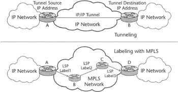
Figure 2.10: MPLS (labeling) versus tunneling.
For instance, at Router B, a mapping between the incoming label, Label 1, and the outgoing label, Label 2, must exist, and a signaling protocol is required to install this information at every node. By contrast, a tunnel can be set up by Operations, Administration, and Maintenance (OA&M) at the edge of the network, and any signaling protocol does not affect intervening routers in the path traversed by packets from ingress to egress point. In addition, LSPs can be set up according to an explicit routed path, thus allowing for traffic engineering to be applied. In other words, the forwarding path can be chosen based on traffic engineering criterions rather than optimal-destination-based forwarding only. The LSP (A, B, C, and D) in Figure 2.10 may have been defined to allow a balanced usage of links from A to B.
Although labeling and tunneling accomplish similar objectives, they have a different—albeit sometimes overlapping—set of applications. Since each hop intervening in the path is affected by MPLS signaling and it has to keep MPLS state, then, intuitively, MPLS cannot be used with the granularity of tunneling technologies. That is, an LSP usually aggregates many more IP flows than a tunnel does. A tunnel can in fact be established between two hosts and dedicated to them only (for example, a VPN client and gateway), and carry traffic meaningful to only these two hosts. MPLS, on the other hand, is normally a router-only technology, since the granularity of an LSP is normally associated with a number of user sessions. In addition, in recognition that MPLS may present scalability issues in core networks, the standards allowed for label stacking, making it possible to aggregate a number of LSPs in the core and switch them according to a common outer label prepended to each individual LSP label.
Although in principle it is possible to recursively tunnel packets—that is, bundle many IP tunnels in an external IP tunnel—this is something that is not often intentionally undertaken, and it happens more by chance, when IP tunnels are carried over another IP tunnel in their end-to-end path. Notably, the label stack concept, illustrated in Figure 2.13, was not germane to the networking industry at the time of the MPLS label stacking proposal, although it was extending only to two hierarchical levels, with ATM VPI-(Virtual Path Identifier) and VCI- (Virtual Circuit Identifier) based switching. ATM allows the definition of virtual-circuit- or virtual-path-based switching. An ATM virtual path can be used to aggregate a number of ATM virtual circuits, and an ATM switch (or cross-connect, if ATM switching information is provisioned via OA&M rather than signaled) used in VP-switching mode can simply forward ATM cells based on the VPI. In fact, one of the first specifications engineers in the IETF made when they were defining MPLS was controlling ATM switches using MPLS signaling (Label Distribution Protocol). The result of their efforts is described in [RFC3035].
MPLS was born from the fusion of multiple proposals from vendors like Cisco Systems, Ascend Communications, and IBM that defined the fundamental concepts and architecture for MPLS-based networks. The intent was to speed up forwarding by replacing IP header lookup with label lookup and augment IP with the capabilities of ATM such as QoS, traffic engineering, and different classes of service. This was the time when Ipsilon Technologies impressed the market with their Ipswitch product that could be used to control ATM switches to bypass the software-based routing process when an IP flow was recognized. Almost at the same time (or rather as a marketing response to it) Cisco came up with TAG switching, which has been, together with Ascend's IP Navigator and IBM's Aggregate Route-based IP Switching (ARIS) at the foundations of the MPLS standardization effort. The proposals on the table were a data-driven approach, where label setup is based on dynamic IP flow recognition, and a control-driven approach, where label setup is based on routing protocols, possibly augmented with some constraints and rules used to engineer traffic, and happening independently and before any packet could flow across the router. The control-driven approach was selected for standardization and shortly became the basis for the protocol development.
The MPLS architecture is based on two classes of MPLS-capable routers: label edge routers (LERs) and label switching routers (LSRs). LERs are placed at the edge of an MPLS domain and classify packets entering the domain in forwarding equivalence classes (FECs). The FEC may be based on destination IP address only, a combination of incoming (virtual) interface and destination IP address, DiffServ IP header marking, multifield classification, and other policies. The LER can be statically configured with a mapping of which label to apply to which FEC, for instance, when complex classification policies are defined locally on the LER. Alternatively, when routing protocols are driving the association of FECs to labels, the association is dynamically and automatically defined.
This property may be used to make the provisioning of multisite VPNs automatic, by applying appropriate BGP extension as described in [RFC2547]. Once packets are classified and a label is assigned to the FEC, the forwarding at the next-hop LSR of the MPLS domain will be based solely on the value of the label. At each intermediate LSR, a label setup protocol populates an information base that defines the association of an incoming interface and label to an FEC and an outgoing interface and label. The label setup protocol may be LDP (Label Distribution Protocol—[RFC3036]) or RSVP extended with MPLS label objects (also known as RSVP extensions for LSP tunnels, [RFC3209]). Note that RSVP and LDP both allow the setup of LSPs along engineered paths via explicit routing objects (RSVP-TE, where TE stands for Traffic Engineering) or via constraints-based routing, like route pinning or explicit routing (CR-LDP, [RFC3212]). Therefore, it is possible to maintain paths with a predictable resources level and deliver predictable service to packets entering the MPLS domain and being delivered to the domain egress LER over known and pre-engineered LSPs.
While describing these and other MPLS options, we purposely avoided a discussion on what differentiates LDP and RSVP, since this issue has always been fairly political and there are, as often happens, no huge technical advantages or disadvantages in using one or the other. There are, however, fairly significant technical differences between them in that RSVP is soft-state-based and LDP is a stateful protocol. RSVP has therefore been seen as generating more signaling traffic and being less scalable than LDP. The industry had been seen leaning toward RSVP-based label distribution for the simple reason that the dominant players in the marketplace had chosen the RSVP path (because of existing investment in this technology). However, recently, LDP seems to be the actual path the industry is following. But again, this may change over time or both approaches may survive equally successfully.
So far we have talked about the ways label information can be distributed, but we have not addressed the equally important topic of how the label information is associated to each packet forwarded between a pair of MPLS-capable nodes. There are two ways to do this. One method is associating the label to the lower-layer protocol fields (e.g., the ATM VPI/VCI fields described in [RFC3035] or the Frame Relay DLCI described in [RFC3034]). The other is inserting a header between the lower layers and the IP protocol, commonly known as the "shim header" approach, described in the MPLS label stack encoding specification [RFC3032]. Note that the shim header approach allows for stacking of labels, thus allowing aggregation of multiple LSPs in a single LSP at different level of hierarchy, which is not uncommon to the current Time Division Multiplexing (TDM) and Synchronous Digital Hierarchy (SDH) hierarchies. A label in the label stack is a 4-octets-long bits-string and it is encoded as depicted in Figure 2.11


