Logical Networks
Transportation networks are made up of physical objects that you can hold or touch with your hand, such as railroad ties and subway rails. Logical network elements do not have these same physical properties as physical networks. Just as virtual reality in video games gives you the illusion of driving a tank or firing a weapon (even though you are not really in a tank or pulling the trigger), logical networks are based on elements that you can't really see or hold, but nonetheless they are there.
A network is made up of several pieces and parts that connect the source and destination. These pieces and parts are grouped into two categories: physical and logical components. It is these physical and logical components that make up the infrastructure and end-user pieces of a network, enabling you to communicate with someone else on the network. Suppose, for example, that you are taking the train from Washington, D.C., to San Francisco. There is a physical and logical component to your trip, as illustrated in Figure 1-3.
Figure 1-3. Physical and Logical Journey from Washington, D.C., to San Francisco
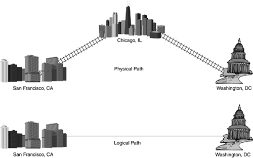
The physical path of your journey takes you from Washington, D.C., to Chicago, where you switch trains to continue to San Francisco. In your mind, however, your trip is logically from Washington, D.C., to San Francisco because you are not staying over in Chicago, merely changing trains. The physical component here are the tracks between the three cities, but the logical component is the starting and ending point of the two cities because you are most concerned with where you start your trip and where your trip ends.
This same physical and logical concept applies to networking and networking components. A brief introduction to these physical and logical components follows.
Network Physical Components
The physical component of a network is a network hardware device, such as a switch and the cabling. This collection of devices and cables, carrying the data from source to destination, makes up the complete physical network.
note
Chapter 5, "Ethernet LANs," discusses switches, bridges, and hubs in more detail. |
Switches
If there isn't a straight route from one city to the next, either the train passengers have to disembark from one train and board another, at a demarcation point (train station), or the trains themselves have to change paths at rail switching stations along the way. Network switches work in a similar fashion by connecting network paths together, providing a route for the frame from source to destination. A switch can also connect one machine to another in a straight path and might be the only path that exists, such as for two PCs connected together in the same room, or for a PC and a networked printer.
Figure 1-4 illustrates the function of a switchyard in a railroad network. A train starting at a distant-end station must go through a railroad switchyard that will change the train's route so that the train can reach its destination train station. In networking, the distant end can be either of the following, depending on the context of the conversation you are having with someone when discussing your network:
The terminating point of the attached network connection
The entire path
Figure 1-4. Railroad Switching Point Between Different Tracks
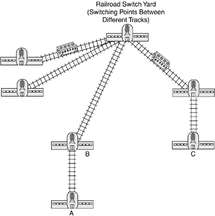
In Figure 1-4, for example, a train leaves from station A, the distant end of the track is station B, and the distant end of the path (ultimate destination of the passengers) is station C. It is important to establish the context when discussing network origination and termination points: Are you discussing the physical connection between two points or the entire path from source to destination?
Figure 1-5 illustrates this same switching concept in a data network, such as you might find in a corporate office.
Figure 1-5. Network Switching Between Paths
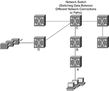
For example, user computers are connected to this network by switch A. To print documents from their computers, the users instruct the application to print. The application then sends the document across the network to the printers connected to switch D. The document to be printed is packaged in a frame and sent out on to the network, where it passes through switch B and switch C and terminates at switch D. Switch D then passes the frame(s) to the printer for the users to retrieve. All this switching, which is transparent to the user, occurs as a result of the user pressing Ctrl-P in a word processor program.
Cabling
To interconnect two or more points, there must be some sort of medium to carry the information from one point to the other, like the railroad tracks between train stations. A medium is defined as the physical substance through which something else is transmitted or carried. Different types of media are used today for network communication, such as copper cable, fiber-optic cable, and the air. (Yes, the same air that we breathe.)
Copper cabling carries electrical signals, such as those generated by computer modems and telephone handsets. Fiber-optic cabling carries light signals, which are transmitted as pulses of light. Imagine turning a flashlight on and off in Morse code. Fiber-optic transmission works in a fashion similar to Morse code, but is much faster and uses a different code. The air carries radio and voice signals, such as the words we speak and the radio broadcasts to which we listen. Simply stated, when people talk, the air between the speaker and the listener is changed, or modulated. The listener's eardrum converts the changes, or demodulates the signal (in this case the voice), so that the listener can understand the signal.
Network cabling connects network devices, such as computers, much as the railroad tracks connect stations within a city or between cities. Without these tracks, the railroad engines and cars would have no way to go from city to city. Without cabling, network devices would not be able to exchange information. If you are deploying a wireless network, however, the communication principles are the same in that each network device must be connected to a wireless transmitter/receiver, or transceiver, for communication to occur).
Network Logical Components
The logical component of a network is the information being carried from source to destination. The user information, which is called data, is carried inside a frame across the network.
Frames
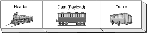
Frames carry the data across the network and are made up of three parts: the header, the data itself, and the trailer. It is these frames that carry user data, just as railroad cars carry passengers. Whereas railroad passengers have tickets specifying their destinations, frames have destination addresses.
Let's look at the functions of the three components of a frame?header, payload, and trailer?by comparing them to railroads:
|  | Train engine carrying source and destination information, such as the source and destination address (identifies the sender of the data and as well as the intended recipient) |
| Train car carrying passengers (user data) | |
| Train caboose signifying the end of the train (frame) |
These components combine to make up a complete frame, as illustrated in Figure 1-6.
Figure 1-6. Complete Frame?Header, Data (Payload), Trailer
User data moves like passengers on a train?they ride the train to reach a destination. Whereas railroad cars carry passengers, network frames carry data. The physical network moves these frames carrying the data from source to destination across the network.


