Flat Network Topology
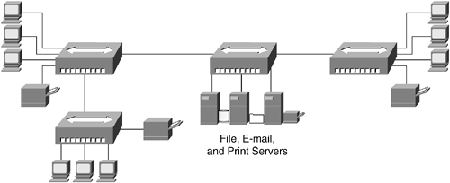
The typical architecture for a small LAN is workstations, printers, and servers attached to one or more hubs or to a small switch in a flat topology, as illustrated in Figure 10-5.
Figure 10-5. Flat Network Topology

The workstations, printers, and servers here use a MAC process, such as Ethernet's carrier sense multiple access collision detect (CSMA/CD), controlling access to the shared bandwidth. These devices are all part of the same bandwidth and broadcast domain and have the capability to impact the throughput of other devices and cause delay in traffic delivery.
For networks with high bandwidth requirements, caused by numerous users and/or traffic-intensive applications, network designers recommend attaching the workstations, printers, and servers to switches rather than hubs. Because hubs work at the physical layer (Layer 1) and switches work at the data link layer (Layer 2), the network is segmented into multiple smaller collision domains. This means that a small number of devices compete for bandwidth at any one time, rather than a "free-for-all" in which everyone competes for the bandwidth.
The number of nodes in a shared-medium LAN and the number of LAN segments are design parameters that should be considered when determining the use and placement of switches or hubs in your network. Because switching is a more expensive solution than using hubs in a shared-medium environment, for some organizations, hubs, or a combination of hubs and switches, might be the best solution. For organizations with high bandwidth and scalability requirements, switches should be used in place of hubs, dedicating each switch port to a single device. The use of switches in this scenario provides dedicated bandwidth to each workstation, printer, or server.
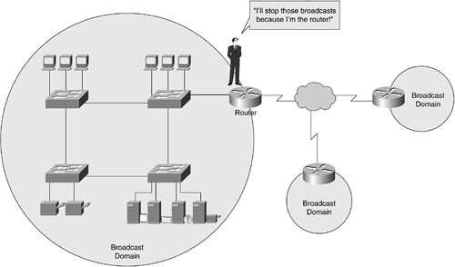
As discussed in Chapter 5, "Ethernet LANs," devices connected in a switched or bridged network are part of the same broadcast domain. Switches forward broadcast frames out all ports (in contrast to routers, which segment networks into separate broadcast domains, as illustrated in Figure 10-6).
Figure 10-6. Routers Separating Broadcast Domains

A single broadcast domain should be limited to a few hundred devices so that these devices are not overwhelmed by the processing of broadcast traffic. Introducing hierarchy into a network design by the addition of routers cuts down on the amount of broadcast traffic sent across the network.
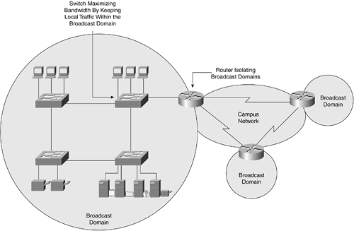
With a hierarchical design, illustrated in Figure 10-7, networking devices are implemented in the network where each does the most good. Routers are added to a campus network design isolating broadcast traffic, and switches are added, maximizing bandwidth for high-traffic applications. Hubs can be used when simple and inexpensive network access is required; switch costs have come down over the years, however, so you should consider a small (low-end) switch rather than a hub. Getting the best performance out of your network is one of the benefits of using a hierarchical design model. Another benefit is that the modular nature of your network helps you in troubleshooting and isolating network faults.
Figure 10-7. Hierarchical Design with Campus-Area Network Core

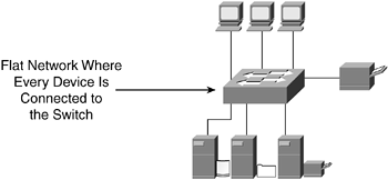
A flat network topology, as illustrated in Figure 10-8, is adequate for small networks and is implemented using Layer 2 switching. This is no hierarchy with a flat network design, and because each network device within the topology is performing the same job, a flat network design can be easy to implement and manage. The flat network topology is not divided into layers or modules and can make troubleshooting and isolating of network faults a bit more challenging than in a hierarchical network. In a small network, this might not necessarily be an issue, as long as the network stays small and manageable.
Figure 10-8. Small, Flat Network

Layer 2 Switching
Layer 2 of the Open System Interconnection (OSI model), the data link layer, provides the reliable transit of data across a physical link. The data link layer is concerned with physical addressing, network topology, line discipline, error notification, ordered delivery frames, and flow control. It is Layer 2 switching that forwards traffic based on the data link, or MAC, layer address. Layer 2 switches support simultaneous, parallel connections between Layer 2 Ethernet segments. Switched connections between Ethernet segments last only for the amount of time it takes for the frame to enter one switch port and leave through another switch port. New connections can be made between different segments for the next frame.
note
For a review of MAC addresses, see Chapter 5. |
Layer 2 switches reduce network-congestion problems in Ethernet networks caused by high-bandwidth devices or a large number of users by assigning each network device to its own Ethernet collision domain. Because each LAN switch port connects to a separate Ethernet collision domain, workstations and servers can benefit from full access to the bandwidth.
Standard Ethernet operates in half-duplex mode and must contend with collisions, which are a major bottleneck. The effective solution is full-duplex communication, enabled by the LAN switch. In full-duplex mode, two stations can transmit and receive at the same time. When frames flow in both directions at the same time, Ethernet bandwidth doubles to 20 Mbps for 10-Mbps ports and to 200 Mbps for Fast Ethernet ports.
Switches operating at Layer 2 are very fast because the switch is sorting traffic based on the physical addresses, but switches are not considered "smart" in that the switch doesn't look at the datagram closely to learn anything more about where it's headed, such as to which network or user.


