OSI Model (As It Applies to LANs and the Interrelation Between Layers)
The upper layers of the Open System Interconnection (OSI) model, where user data is found, need the lower layers, like a train needs tracks to get from point A to B. It is these lower layers?physical, data link, and network?that provide the "railroad tracks" for the user data. They allow the data to ride across the network, such as when sending an e-mail or surfing the Internet.
Layer 1?Physical Layer
The physical layer moves the bit stream (signal) from one point to another across a carrier, such as a network cable, originating from the transmitter (device sending the signal) and terminating at the receiver (device receiving the signal). For example, when you have a telephone conversation with someone, your mouthpiece is the transmitter and the other person's earpiece is the receiver. The signal is either an electrical impulse when carried over copper, light when carried over fiber-optic cabling, or a radio signal when carried through the air.
The physical layer is made up of the following:
Signal? The data being carried in the form of bits (1s and 0s), which are converted into electrical impulses (sine wave), radio signals, or pulses of light
Hardware? A transmitter, receiver, repeater, regenerator, or a hub
Media? Coaxial (coax), fiber-optic, or copper (shielded and unshielded twisted-pair) cabling; and air for wireless signals
In a LAN environment, the physical layer components are the network interface card (NIC) in your computer, the cable connecting your computer to the network, and the signal being sent by your NIC across the cable.
Signal
The signal, with respect to cabling, is the information being sent across the medium in an electronic or optical (light) fashion.
There are two types of electronic signals: analog and digital. Analog signals are represented as continuous waves, as illustrated in Figure 3-4.
Figure 3-4. Analog Signal Wave

In contrast to the continuous wave of an analog signal, digital signals consist of values measured at discrete intervals, or square waves, as illustrated in Figure 3-5.
Figure 3-5. Digital Signal Wave

The difference between analog and digital can be best demonstrated by looking at both an analog and a digital watch, as illustrated in Figure 3-6.
Figure 3-6. Analog and Digital Watches
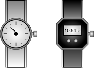
Digital watches display one value (10:54) and then the next (10:55) without showing all the intermediate values between the two. Digital watches, therefore, display only a finite number of times of the day, such as every minute. In contrast, the hands of analog watches move continuously around the clock face. As the minute hand goes around, it not only touches the numbers 1 through 12, but also the infinite number of points in between, indicating every possible time of day.
We experience the world in an analog fashion; vision is analog because we perceive infinitely smooth gradations of shapes and colors. Speech is analog because there are infinite variances in tone and pitch that make up the sounds we hear. Most analog events, however, can be simulated digitally (the photographs in newspapers, for instance). Although these photos are made up of arrays of discrete black or white dots (digital form), when we look at the photographs we perceive lines and shading that appear to flow into each other to form images. In this way, we perceive a digital image as an analog picture. Although digital representations are approximations of analog events, they are useful because they are relatively easy to store and manipulate electronically. As shown in Figure 3-7, the idea here is that analog is free flowing, whereas digital is exact.
Figure 3-7. Analog-to-Digital Conversion

This same principle of digital information being presented as analog is the principle behind compact discs (CDs). The music exists in an analog form as waves in the air, but these sounds are then translated into a digital form that is encoded onto the disc as 1s and 0s. When you play a compact disc, the CD player reads this digital data, translating the 1s and 0s back into a form of music (audio vibrations) that we hear from our stereo giving the perception of the original analog music.
note
The term bit (short for binary digit) was first used in 1946 by John Tukey (1915?2000), a leading statistician and adviser to five U.S. presidents. (If you win money in a trivia contest for knowing this, please contact me and we can split the winnings.) |
To send and receive these signals across a medium, we need network hardware.
Hardware
A transmitter is the device sending the signal, a receiver is the device receiving the signal, and a repeater is a network device used to copy or boost a signal on the path between the transmitter and receiver. Repeaters are used in transmission systems to regenerate analog or digital signals distorted by transmission loss. Analog repeaters amplify the signal, whereas digital repeaters reconstruct the signal to its near-original quality, as shown in Figure 3-8. Analog and digital repeaters amplify any noise on the line as well as the signal. Regenerators amplify the signal but not the noise. However, regenerators are often more costly to implement than repeaters. Repeaters and regenerators can be used for electronic, optical, and wireless signals, and are used extensively in long-distance transmission. Repeaters are used to tie two LANs of the same type together, such as two Ethernet LANs.
Figure 3-8. Repeater

Hubs are often used to connect small LAN segments where the number of devices generally is 24 or fewer. Hubs are multiport repeaters, and when a frame arrives on one port, it is repeated to the other ports so that all segments of the LAN can see all frames, as illustrated in Figure 3-9.
Figure 3-9. Hub
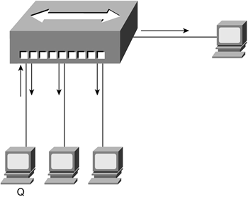
Figure 3-9 shows Host Q sending traffic, in the form of frames, out to the network via a port on the hub. These frames are received by the hosts connected to the same hub, including the host that sent the traffic to begin with, Host Q. Host Q, knowing what it sent, ignores what comes back. The other hosts, however, must read each frame to determine whether they are the intended recipients. If it helps you to understand the process shown in Figure 3-9, you can think of it as being similar to mail arriving for everyone in your office in separate envelopes. Each person receiving an envelope reads the name and address to determine whether the mail is in fact for him. To return to the electronic example?if you are in a small office, with a few people, this is not so bad; in a larger office, however, the process becomes cumbersome because it slows the network down with all the additional traffic.
Each host connects to a network device, be it a hub, bridge, or switch, via some sort of medium, as discussed in the next section.
Media
The network medium provides the physical connection between the sender and the receiver. Air is the medium used for wireless communications, and cabling is the medium used in wireline (nonwireless) communications. The three types of network cabling in use today are as follows:
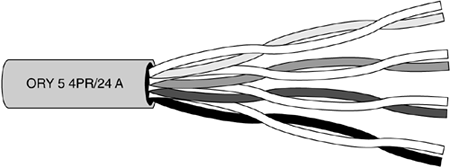
Twisted-pair cable, which is illustrated in Figure 3-10, comes in two cabling options?unshielded twisted-pair (UTP) and shielded twisted-pair (STP).
- UTP is a popular type of cable made up of two unshielded wires twisted around each other. Due to its low cost, UTP cabling is used for LAN and telephone connections. UTP cabling does not provide for high bandwidth or good protection from electromagnetic interference (EMI) such as coaxial or fiber-optic cabling provides. EMI is an electrical disturbance caused natural phenomena (such as lightning), low-frequency waves from electromechanical devices, such as disk drives and printers, or high-frequency waves (radio frequency interference, RFI) from chips and other electronic devices, such as central processing units (CPUs).
- STP is a type of copper telephone wiring in which each of the two copper wires is twisted together and coated with an insulating coating functioning as a ground for the wires. The extra covering in STP wiring protects the transmission line from EMI leaking into or out of the cable, resulting in signal degradation or loss.
Figure 3-10. Twisted-Pair Cable
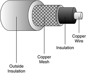
Coaxial cable, illustrated in Figure 3-11, is a type of wire carrying electrical impulses that consists of a center wire surrounded by insulation and then a grounded shield of braided wire. The shield minimizes EMI and RFI and is the primary cabling type used in the cable television (CATV) industry.
Figure 3-11. Coaxial Cable
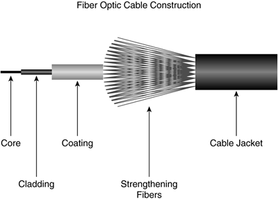
Fiber-optic cable is a type of cable using glass or plastic threads (fibers) to transmit data. As illustrated in Figure 3-12, fiber-optic cable consists of a bundle of glass threads, each of which transmits messages via light waves. This glass is encased in cladding and coating, reinforced by strengthening fibers and further wrapped within a cable jacket.
Figure 3-12. Fiber-Optic Cable
Layer 2?Data Link
So far, this chapter has discussed the types of signal and media that are found at Layer 1 of the OSI model, but you might be asking yourself, "What are these signals carrying?" The signals are carrying user data in the form of frames. Frames are found at Layer 2 and move data around the network. It is the network topology that determines which devices these frames can be exchanged among.
Have you ever bought a "one size fits all" hat that you couldn't squeeze onto your head? The arrangement, or topology, of a network is much the same; there is no "one size fits all." Each topology serves its own purpose, and it is this purpose that determines what size fits. For example, let's revisit the railroad from Chapter 2, "Networking Models and Standards," for a moment. If all the cities needed to be directly connected with one another, a full mesh topology might be used because a direct path between each city would be available. A star topology might also be used in which each city would directly connect to a central place where the trains would switch tracks.
This same connectivity concept applies to data networks. If hosts on the network need to communicate directly with each other, a full-mesh topology is the answer. (For a description of full-mesh topology, see Table 3-1.) However, this is not often the case; instead, it is more common to see each host communicate through a central point, as in a star topology.
Topology | Description | Figure | When to Use |
|---|---|---|---|
Full mesh | Devices are connected with many redundant interconnections between network nodes. In a true mesh topology, every node has a connection to every other node in the network. |  | Hosts need to talk directly with each other. This topology might be used in a peer-to-peer environment where frequent file sharing is required. The challenge here is the number of connections each host has to maintain. A formula used to determine the number of links required in a full-mesh network: (n * (n ? 1))/2 or (n2 ? n)/2 n is number of nodes. In a WAN environment, a full-mesh topology might be used in virtual private network (VPN) environments where it is easy to configure multiple sites connected to each other. |
Star | All devices are connected to a central hub. Nodes communicate across the network by passing data through the hub. |  | This is a common LAN topology. In a star topology, all LAN devices connect to a centralized point, such as a hub or a switch. This central point enables each host to talk to the other hosts but not in the direct fashion afforded in the full-mesh topology. The advantage of the star over the full-mesh is that each host has one connection to maintain, not several. One drawback to this topology is that the central point is a single point of failure; if this point fails, all connected devices are also down. A formula used to determine the number of links required in a star network: n ? 1, where n is the number of nodes. In a WAN environment, a star topology might be used to provide connectivity to multiple remote locations, such as remote offices in a corporate network. |
Ring | All devices are connected to one another in the shape of a closed loop, so that each device is connected directly to two other devices, one on either side of it. |  | The ring topology is often used when there is a redundancy requirement. Therefore, if a network segment fails, each network device can continue to communicate with the others around the ring. A ring topology might be used to provide metropolitanarea network (MAN) connectivity, possibly using WDM. |
Tree | A hybrid topology. Groups of star-configured networks are connected to a linear bus backbone. |  | The tree topology is used when a hierarchical network is desired to group users together, such as by geographic location or by function, such as accounting or sales. This topology is often seen in WAN environments. |
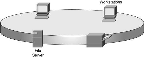
Remember the OSI model? We're never very far from it during any network discussion, and topology discussions are no different. Each layer of the OSI model could have its own topology. For example, each network device could be physically connected in a star topology to a central device but logically work as a ring topology. This type of Token Ring implementation is illustrated in Figure 3-13 and Figure 3-14.
Figure 3-13. Token Ring Physical Topology
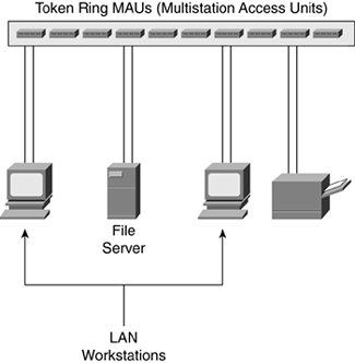
Figure 3-14. Token Ring Logical Topology
Frames
Recall the discussion of frames from Chapter 1, "Networking Basics." Frames carry data across the network and are made up of three parts: the header, the payload itself, and the trailer. It is these frames that carry user data (packets) just as railroad cars carry passengers. Whereas railroad passengers have tickets that specify their destinations, data-link frames have destination addresses specifying where the frame should go. The following table outlines the three components of a frame and their respective functions.
Frame Component | Function |
|---|---|
Header | Signifies the start of the frame and carries Layer 2 source and destination address information |
Payload | Carries data from Layer 3, such as packets from the network layer containing user data |
Trailer | Signifies the end of the frame and carries error-detection information in the form of a cyclic redundancy check (CRC) |
The three frame components?header, payload, and trailer?combine in making up a complete frame, as was illustrated in Figure 1-6 in Chapter 1.
Much as a train consists of the engine, passenger/cargo car, and caboose, the frame is made up of a header, payload, and trailer. Whereas the train engine determines which track, or path, the train takes, the frame header determines which path through the network the frame follows. The data (payload) carries the information just as the passengers are carried by the train. The trailer identifies the end of the frame, just as the caboose identifies the end of the train.
Just as the railroad train moves around the country, so too do frames move around the network across the tracks. These tracks are often interconnected with bridges, connecting track segments to form longer rail lines; and railroad switches provide a way for each train to change tracks, or direction. Network bridges and switches work in much the same fashion as the bridges and switches in the railroad and are discussed in more detail in the next section.
Hardware
As mentioned earlier in this chapter, repeaters work at Layer 1 (physical) by repeating the signal received from the transmitting side out to the receiver and vice versa. This type of repeater has two ports?one for each direction.
If multiple devices need the benefits of a repeater, however, a hub is used because a hub is a multiport repeater. Recall that with a hub, a signal received on one port is repeated out all ports. Much as a hub is a multiport repeater, a bridge is a multiport hub. Bridges connect two LANs or two segments of the same LAN using the same protocol, such as Ethernet. Bridges learn from experience and build and maintain address tables of the nodes on the network, called Media Access Control (MAC) tables. By monitoring the LAN, the bridge learns which hosts belong to which segment and builds a table using the source MAC address of the frames, as they come in to the bridge.
Bridges work at the data link layer (OSI Layer 2) and are protocol independent. Bridges with more than two ports (multiport bridges) perform switching functions. Switches also work at the data link layer and, like bridges, are protocol independent.
A bridge is considered a multiport hub, whereas a switch is considered to be a multiport bridge with multiple network segments that might, or might not, communicate with each other. Switches also build tables based on the MAC address received on each switch port and forward frames based on these tables.
Figure 3-15 illustrates the use of bridges and switches in a data network and in a railroad network.
Figure 3-15. Network Bridges and Switches
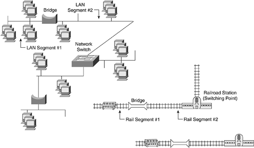
In a railroad network, bridges connect separate track segments to create a single "network" of tracks from the smaller track segments. Sometimes these trains change tracks at a railroad switchyard or station, with the passengers still on board. Other times the trains go back and forth between stations with the passengers switching between trains. If the passengers are not at their intended destination and need to continue their journey, they do not stay on the same train and try to convince the engineer to keep going. They change trains at the train station.
The train stations provide a switching point for the passengers riding these trains and sometimes the trains themselves. If a passenger needs to ride several trains to get from the originating (starting) point to the terminating (ending) point, the passenger switches trains at the railroad station. How does the passenger know which train to board at the railroad station? The answer is found in the train ticket, which states the originating and terminating points (start and destination).
When you arrive at the train station, with ticket in hand telling you where you are going (in case you forgot), you look at the train departure board to determine from which track your train is departing. When you know which track, you go to the gate, board the train, and continue your journey, repeating these steps until you arrive at your intended destination.
A train switching tracks with the passengers still aboard is similar to frames being switched between LAN segments (Layer 2 switching). When the passengers disembark and board another train at the train station, with ticket in hand telling them where to go, this is similar to packets being routed between network segments (Layer 3 routing).
note
Chapter 5, "Ethernet LANs," discusses Layer 2 hardware and operation in more detail. |
Layer 3 and Above
The logical topology at Layer 3 (network) is made possible by the logical topology at Layer 2 (data link) and the physical topology at Layer 1 (physical) underneath it all. A packet has to and from addresses (destination and origination), much as a letter has sending (return) and receiving addresses. The letter does not concern itself (as much as a letter is "concerned") with how it gets from sender to receiver because it has a logical "straight line." The letter, or packet, is not aware of the lower logical and physical layers that comprise the line of direction, just that the letter has a path to get to its intended destination, as illustrated in Figure 3-16.
Figure 3-16. Logical and Physical Topology of a Letter's Travels
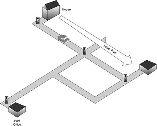
The physical topology is illustrated by the roads between the house and the post offices. This physical topology is broken down into segments by the traffic lights at various points along the way. The logical topology here is the straight line from the house to the post office, unaffected by the roads traveled or the traffic signals along the way. The letter's transmission from house to post office is affected here when there is no physical path at all, such as all available roads closed or blocked.
Packets
Because packets and frames work at different layers (Layer 3 and Layer 2 respectively), they involve different aspects of the network. Think of a frame as a train engineer?he needs to know where to go and how to get there and is not concerned with where the train has just left. A packet needs to know where it is going and from where it came, much as a letter needs to have the recipient's address and the sender's address. The recipient in turn uses the return address to send a reply.
note
A packet is a fixed block of data sent as a single entity across a network. Commonly when LANs are discussed, the terms frame and packet are used synonymously. However, packets are found in the network layer (Layer 3 of the OSI model), and frames are at the data link layer (Layer 2 of the OSI model). |
Packets are only affected by the underlying physical and logical topology if a failure results in the path being broken. For example, suppose you have three roads between home and work and at any time you can take any one of those roads. One morning one of those roads is closed for construction; the physical path is unavailable for use. The physical topology for your drive has changed because now two roads are available rather than the original three. You are not concerned here because you still have a way to get from home to work. Your logical path has not changed; it is still home to work, but the physical topology has changed in that now you have to take a different road. Network packets work in the same way. It is the routers and Layer 3 switches that decide over which path the packets move, making the decisions just as you would behind the wheel of the car.
Hardware
Hubs and repeaters are found at Layer 1, bridges and switches and found at Layer 2, and routers are found at Layer 3. A router is a network device that receives and forwards data packets along a network. A router connects two or more networks together; often these are WANs, but routers can also be used to connect two or more LANs. The most common placement of a router is between a LAN and a WAN, such as the Internet, as illustrated in Figure 3-17.
Figure 3-17. Router Connecting a LAN and the Internet
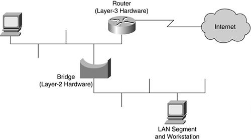
Routers work at Layer 3 of the OSI model to examine the header of each packet. From the header the router determines the path on which the packet must be forwarded. This is similar to the decision you make when you look at an arrival and departure board in the train station to determine on which track your train departs. Routers determine pathways for packets based on routing tables.
The common theme here is that you make a determination based on a table of information, and routers make a determination based on a similar table of information, called a routing table.


