Root Bridge or Switch Port
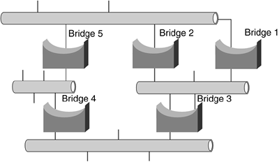
STP has a root and branches like a tree. The primary decision-making switch in an STP environment is called the root bridge. The network flows out from the root bridge to form a logical branched network. All switches in a LAN participating in STP branch from the root switch port or bridge. In Figure 7-2, Bridge 1 is the root bridge, and all connected segments branch from this root.
Figure 7-2. Five-Bridge Network with Root Bridge (Bridge 1)

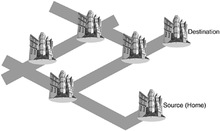
The first task of the STP is determining where the spanning tree begins?the root bridge or switch port. The root bridge is used to build a reference point in the network so that the spanning-tree algorithm can be calculated. All paths from all bridges and switches must be traceable back to the root bridge or root switch, much as all roads lead to or from your hometown, regardless of how many other towns you travel through to reach your destination, as illustrated in the Figure 7-3.
Figure 7-3. Multiple Routes Between the Source and Destination

The root switch is elected as part of the STP and is necessary to build a reference point for the spanning-tree algorithm calculations. All paths not needed to reach the root switch network are placed in backup mode. Each switch in the network gathers information about other switches in the same network through an exchange of data messages called bridge protocol data units, or BPDUs.
Bridge Protocol Data Units (BPDUs)
Bridge protocol data units, or BPDUs, are data messages exchanged between the switches and bridges within an extended LAN using the STP. BPDU frames contain information regarding the originating switch port, Media Access Control (MAC) address, switch port priority, and the switch port cost. The cost of a switch port is based on the number of network segments the frame crosses before reaching its destination.
BPDU messages are also exchanged across bridges and switches to detect loops in the network topology. Any loops found are removed by shutting down the selected bridge and switch interfaces and placing the redundant switch ports in a backup, or blocked, state.
The topology of a switched LAN is determined by the following:
The unique switch identifier or bridge ID associated with each switch? The bridge ID is made up of the MAC address and the bridge priority. As your home telephone number is unique so that you can be reached by anyone looking for you, so must the identifier of each switch be unique so that it can be found in the network.
note

The MAC address is the 48-byte hardware address of the network interface.
The port cost associated with each switch port? The port cost is for communication between the switch port and the root port. This is true whether it is a financial cost, as in your long-distance telephone calls, or a logical cost, as in how fast (maximum bandwidth) each network segment is that the frame must cross on its way from source to destination.
One BPDU is superior to another if it has a lower
Root bridge ID
Path cost to the root
Sending bridge ID
Sending port ID
Each switch originates, but does not forward, configuration BPDUs that are used to compute the spanning-tree topology. The BPDU frame is sent across the LAN, and all connected bridges and switches receive this BPDU. The receiving switch uses the information in the BPDU to determine changes in the network topology. If there is a change, the receiving switch sends a new BPDU across all attached network segments.
BPDUs contain information about the sending switch and its ports, including the following:
Switch and port MAC address? This is the MAC address of each switch and bridge port that is part of the tree.
Switch and port priority? When switches and bridges are running the STP, each has a bridge or switch port priority associated with it. By default, all STP switches are configured with a bridge priority value of 32,768. After the exchange of BPDUs, the switch with the lowest priority value becomes the root bridge.
Port cost? Cost is determined according to the speeds that the ports support; the faster the port, the lower the port cost. Switches use port costs in determining the root port for each and every switch.
The exchange of BPDUs results in the following:
One bridge or switch port is elected as the root bridge/switch port. This election is similar to a bunch of switches going to a voting booth and choosing their favorite switch. The BPDUs are used as a voter information guide, or ballot, to select the correct candidate. The purpose of this election is to determine which switch has the lowest identifier.
The shortest distance to the root switch is calculated for each switch. Recall that the shortest distance between two points is a straight line, and the exchange of these BPDUs determines the direction of the straight line between bridge/switch ports.
A designated switch is selected. This designated switch is the closest switch to the root switch through which frames will be forwarded to the root. There is only one designated switch per segment or VLAN.
A designated port for each switch is selected, providing the best path to the root switch. Every LAN segment needs to know which switch is its entry/exit point to the rest of the network; otherwise, frames would wander aimlessly around the same network segment, never getting anywhere.
Ports included in the STP are selected. Because all ports might not be part of the spanning tree, the exchange of BPDUs determines which ports have an invitation to the spanning tree (forwarding) and which ports do not. (Those that don't are disabled.) If STP is not running on some ports or switches, loops can occur on those non-STP ports, which then circumvent the STP blocks.
note

All bridge/switch ports are included in the STP BPDU message. The ports not turned on are not included as part of the spanning tree.
Loops in the switched network are removed. Loops are detriments to networks because traffic on a network containing loops goes around in circles?stuck on the proverbial hamster wheel?and can shut down the network. These network loops are prevented by each switch placing redundant switch ports in a backup state as directed by the STP.
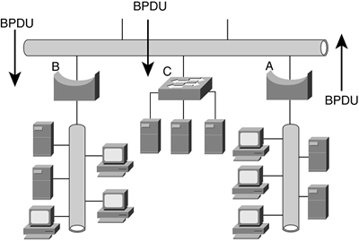
The following figure illustrates how BPDUs enable a spanning-tree topology based on the STP. Bridge A sends out a BPDU across the network that is received by Bridge B and Switch C.
Figure 7-4. BPDU Exchange Establishing the Spanning-Tree Topology


