Introducing Spanning Tree Protocol
As with traditional shared Ethernet, transparent bridges inherently lack the capability to provide redundancy. The Spanning Tree Protocol (STP) inserts a mechanism into the Ethernet transparent bridge environment to dynamically discover the network topology and ensure only one path through the network. Without STP, there is no way to make a transparent bridge environment redundant. STP also protects a network against accidental miscablings because it prevents unwanted bridging loops in the transparent bridging environment. A bridge loop is similar to a wrestling match. At first, everything appears orderly, but pandemonium soon ensues. The normal referee and rules do not work. The pandemonium does not stop until someone comes in and shuts the match down. Bridge loops in Ethernet and transparent bridging also cause pandemonium. Figure 1-13 shows a bridge loop in Ethernet.
Figure 1-13. Bridging Loop
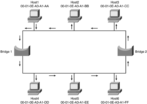
In this basic example, there are redundant links without STP. This creates a bridged loop. In this case, the redundant links cause the Ethernet data frame to have more than one path. Because the bridges are transparent, a copy of the data frame is sent across both paths. Bridge1 and Bridge2 both receive a copy of the data frame that was sent by the other. Then, each bridge sees alternating data frames, assumes that the source host is on the wrong side of the bridge, and updates the bridge table. The data frames then start to be recopied on each side of the bridge again and again. Think about how many data frames are needed for a simple e-mail message. With this bridging loop, the frames would be copied over and over again until they timed out. However, because the upper layer protocols are generating many requests, the process keeps happening. The entire network gets overwhelmed and legitimate traffic cannot pass.
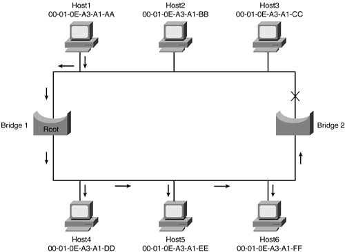
Figure 1-14 revisits the example again, this time adding STP, which blocks one of the redundant links, eliminating the bridging loop. If the first link or Bridge1 were to fail, STP would re-examine the network and enable the shutdown connection. This is how STP provides redundancy in a transparent bridging environment.
Figure 1-14. Spanning Tree Blocking
NOTE
Be aware that the spanning-tree algorithm is implemented in other media types such as Token Ring. STP has a different purpose and function in Token Ring than in Ethernet because bridging loops can be desirable in Token Ring.
Spanning Tree Operations
STP operation for each bridge can be broken down into three main steps:
Root bridge selection
Calculation of the shortest path to the root bridge
Type of role an active port plays in STP
The main information to be concerned with is the Root ID (bridge that the transmitting bridge thinks is the root), Bridge ID, and cost (which is the cost to the root bridge). The STP topology is considered converged after a root bridge has been selected and each bridge has selected its root port, designated bridge, and which ports will participate in the STP topology. STP uses these configuration messages (BPDUs) as it transitions port states to achieve convergence.
Spanning tree elects one bridge on the LAN to be the master bridge. This bridge is called the root bridge. The root bridge is special because all the path calculation through the network is based on the root. The bridge is elected based on the Bridge ID (BID), which is comprised of a 2-byte Priority field plus a 6-byte MAC address. In spanning tree, lower BID values are preferred. In a default configuration, the Priority field is set at 32768. Because the default Priority field is the same for all the bridges, the root selection is based on the lowest MAC address. One method of selecting a specific bridge to be the root is to manually alter the Priority field to a lower value. Regardless of what the MAC address is, the Priority field decides what bridge is going to be the root, assuming that all bridges do not have the same priority value. For the remainder of this chapter, the figures depict a switch, which at its fundamental level is a glorified bridge. (See Figure 1-15.)
Figure 1-15. Switch1 Becomes Root
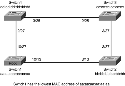
Each bridge calculates all the paths from itself to the root. It then selects the shortest path. The next-hop bridge toward the root is the designated bridge. The port that leads to the designated bridge is selected to be the root port because it is closest from this bridge to the root bridge. The metric that STP uses for this determination is cost, which is based on the interface speed. Table 1-8 compares bandwidth to STP interface costs.
Bandwidth | Cost |
|---|---|
4 Mbps | 250 |
10 Mbps | 100 |
16 Mbps | 62 |
45 Mbps | 39 |
100 Mbps | 19 |
155 Mbps | 14 |
622 Mbps | 6 |
1 Gbps | 4 |
10 Gbps | 2 |
As shown in Figure 1-16, Switch3 has two paths to the root. To prevent a loop on the network, it must decide to block one of its ports. The algorithm used to make the decision is based on three choices:
Lowest path cost to the root
Lowest sender BID
Lowest port ID
Figure 1-16. Converged Spanning-Tree Topology
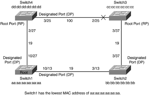
In this example, the lowest path cost to the root will decide which port will be forwarding and which one will be blocking. Because the cost is less through Switch2 path, 38, Switch3 will be forwarding out of this port and blocking on the other. This behavior of blocking a port allows the spanning tree to be loop free and provide redundancy should one of the ports go down.
Each active port can have a specific role to play in the spanning-tree algorithm:
Designated Port (DP)? The port responsible for sending BPDUs on the segment
Non-Designated Port (N-DP)? Does not send BPDUs on the segment
Root Port (RP)? The closest port to the root
STP sends configuration messages out every port of the bridge. These messages are called bridge protocol data units (BPDUs). BPDUs contain the appropriate information for STP configuration. The Type field for BPDU message is 0x00, and it uses the multicast MAC address 01-80-C2-00-00-00. The BPDU packet is shown in Figure 1-17.
Figure 1-17. Bridge Protocol Data Unit Format

Spanning Tree Port Transitions and Timers
Part of the STP algorithm and process of building a loop-free network, as well as reconfiguration on a topology change, is to cycle the bridge ports through several states, as follows:
Blocking? A port is placed in blocking mode upon startup and when STP determines it is a suboptimal path to the root bridge. Blocked ports do not forward traffic.
Listening? When a port is transitioned from blocking to listening, it starts to listen for other bridges. It does not send out configuration messages, learn MAC addresses, or forward traffic.
Learning? The bridge continues to listen for other bridges; however, it can now also learn MAC addresses of network devices.
Forwarding? This is normal operation. Data and configuration messages are passed through the port.
STP uses timers to determine how long to transition ports. STP also uses timers to determine the health of neighbor bridges and how long to cache MAC addresses in the bridge table.
The explanation of the timers is as follows:
Hello timer? 2 seconds. This timer is used to determine how often root bridge sends configuration BPDUs.
Maximum Age (Max Age)? 20 seconds. This timer tells the bridge how long to keep ports in the blocking state before listening.
Forward Delay (Fwd Delay)? 15 seconds. This timer determines how long to stay in the listening state before learning, and the learning state before forwarding.
The STP timers can be tuned based on network size. These parameters are designed to give STP ample opportunity to ensure a loop-free topology. Mistuning these parameters can cause serious network instability. Tuning these parameters will be discussed in Chapter 10, "Implementing and Tuning Spanning Tree." When a bridge sees BPDUs with a better path to the root, it recalculates STP. This allows ports to transition when appropriate.
Topology Changes in STP
The other type of STP BPDU that needs to be discussed is Topology Change Notification (TCN). TCNBPDU is generated when a bridge discovers a change in topology, usually because of a link failure, bridge failure, or a port transitioning to forwarding state. The TCN BPDU is set to 0x80 in the Type field and is subsequently forwarded on the root port toward the root bridge. The upstream bridge responds back with acknowledgment of the BPDU in the form of Topology Change Acknowledgment (TCA). The least significant bit is for TCN, and the most significant bit is for TCA in the Flag field.
Figure 1-18 shows the flow of topology change BPDUs. The bridge sends this message to its designated bridge. Remember, the designated bridge is a particular bridge's closest neighbor to the root (or the root, if it is directly connected). The designated bridge acknowledges the topology change back to the sending neighbor and sends the message to its designated bridge. This process repeats until the root bridge gets the message. The root learns about the topology changes in the network in this way.
Figure 1-18. Topology Change Because of a Link Failure
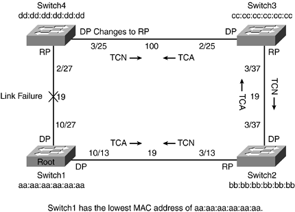
By default, bridges keep MAC addresses in the bridge table for 5 minutes. When a topology change occurs, the bridge temporarily lowers this timer to the same as the forward delay timer (default: 15 seconds). This allows the STP network to react to changes in topology by having the bridges quickly relearn the MAC address changes that occur when links change state. Without this, network devices could be unreachable for up to 5 minutes while the bridge ages the MAC address out. This is typically called a black hole because data is forwarded toward a bridge that no longer can reach the network device. Topology change BPDUs are a mechanism to overcome this. A common misconception is that topology change BPDUs cause STP to recalculate. The purpose of topology change BPDUs is to avoid black holes and allow the bridges to have up-to-date bridge tables. STP recalculations only occur only when the bridge sees BPDUs with better paths through the bridged network or when the bridge no longer receives configuration BPDUs from the root bridge.
This section offers a simple introduction to spanning tree. Later chapters include examples of the complexities of spanning tree and the various enhancement features available.


