UniDirectional Link Detection
Although the UniDirectional Link Detection (UDLD) protocol falls outside of STP, UDLD has numerous benefits that make it essential in a Layer 2 network. UDLD's function is to prevent a one-way communication between adjacent devices. When UDLD detects one-way conversation, it can do one of two things depending on whether UDLD is configured in Normal mode or Aggressive mode. In Normal mode, UDLD simply changes the UDLD-enabled port to undetermined state if it stops receiving UDLD messages from its directly connected neighbor. Aggressive mode was introduced in Catalyst OS 5.4(3); it will make eight attempts to re-establish the UDLD neighbor relation before error disabling the port. Aggressive mode is the preferred method of configuring UDLD. Bottom line, by preventing this one-way communication, UDLD can be very useful in spanning-tree networks.
UDLD was first introduced in Catalyst OS 5.1(1). UDLD is a Layer 2 protocol that is enabled between adjacent switches. It uses MAC 01-00-0c-cc-cc-cc with SNAP HDLC protocol type 0x0111. Example 10-31 illustrates the UDLD packet format.
Example 10-31. UDLD Packet
Multicast Address:      01-00-0c-cc-cc-cc

LLC:                            0xAAAA03

Org ID:                        0x00000c

HDLC Protocol Type: 0x0111

       TVLs (Type Length and Value):

        0x0001:         Device ID

        0x0002:         Port ID

        0x0003:         Echo LV

        0x0004:         Message Interval TLV

        0x0005:         Timeout Interval TLV
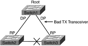
For example, in Figure 10-19, the TX transceiver from Switch1 goes faulty and is not sending configuration BPDUs to Switch3. To make matters worse, Switch1 is not detecting the faulty transceiver and, as a result, it will not bring the port down. Because Switch3 is not receiving the BPDUs, it assumes that it has lost its connection to the Root. It will transition its blocking port to forwarding state. It will change its original RP that was directly connected to Switch1 to DP. Switch3 will assign the port that is connected to Switch2 as its RP. The network now is no longer loop free. A potential for a counterclockwise one-way loop exists. If a host from Switch2 sends a broadcast message, both Switch1 and Switch2 will receive the broadcast. Switch3 will forward the broadcast to Switch1, which, in turn, will forward it back to Switch2, and so on. UDLD, in Aggressive mode, helps spanning tree in this type of an event by error disabling the port.
Figure 10-19. Bad Transceiver

The two adjacent devices send UDLD packets at intervals of 15 seconds. The packets are echoed back by the adjacent switch to its neighbor, informing the upstream switch that it received the UDLD message. In Example 10-32, Switch1 receives a UDLD packet from Switch2's port 1/1. Because it received a UDLD packet, Switch1 will reset its UDLD neighbor cache table. The function of the UDLD neighbor cache table is to ensure that the neighbor is still active. If the cache table times out, UDLD will error disable the port as is in the case of Aggressive mode. Any time a UDLD message is received, the cache table timers are reset.
Example 10-32. UDLD syslog Message
Switch1 (enable) UDLD(1,2)Rcvd msg #1 from TBA04081025(Switch#2) port 1/1

UDLD(1,2)Found my own ID pair in 2way conn list

UDLD(1,2)Udld packet memory released

UDLD(1,2)[80974]InbandTransmit succeeded

UDLD(1,2)[81343]Received packet, parsing...

UDLD(1,2)New_entry = 835f2e90

UDLD()Entry added: 2 entries cached
UDLD needs to be first globally enabled, and then at the port level running Catalyst OS code, as shown in Example 10-33.
Example 10-33. Enabling the UDLD Feature
Switch1 (enable) set udld enable

UDLD enabled globally

Switch1 (enable) set udld enable 1/2

UDLD enabled on port 1/2.

Warning: UniDirectional Link Detection should be enabled on all

 the ends of the connection in order to work properly.
Table 10-3 shows the four different types of port states defined by UDLD. To check a port's link state, use the show udld port command, as shown in Example 10-34.
Example 10-34. Display UDLD Configuration for Port 1/2
Switch1 (enable) show udld port 1/2

UDLD              : enabled

Message Interval  : 15 seconds

Port      Admin Status  Aggressive Mode  Link State

--------  ------------  ---------------  ----------------

 1/2      enabled       disabled         bidirectional
Port State | Function |
|---|---|
Undetermined | Currently attempting to detect neighbor or neighbor is not configured for UDLD. |
Not Applicable | UDLD is disabled on the port. |
Shutdown | UDLD is detected and port is shutdown. |
Bidirectional | UDLD is working fine. Adjacent devices see each other's UDLD messages. |
Example 10-35 is a hidden command that shows the UDLD state of the neighbor. The output shows the neighbor is in bidirectional state with Switch1.
Example 10-35. Hidden UDLD Command
Switch1 (enable) show udld neighbor

Port     Device Name                    Device ID    Port-ID OperState

-------- ------------------------------ ------------ ------- --------------

 1/2     TBA04081025(Switch2)          00016329bc00 1/1     bidirectional
Finally, Example 10-36 shows how to configure UDLD for Aggressive mode.
Example 10-36. Enabling UDLD Aggressive Mode
Switch1 (enable) set udld aggressive-mode enable 1/2

Aggressive UDLD enabled on port 1/2.

Warning: Aggressive Mode for UniDirectional Link Detection

should be enabled only on ports not connected to hubs,

media converters or similar devices.

Switch1 (enable) show udld port 1/2

UDLD              : enabled

Message Interval  : 15 seconds

Port      Admin Status  Aggressive Mode  Link State

--------  ------------  ---------------  ----------------

 1/2      enabled       enabled          bidirectional


