Building Blocks
When designing a switched network, following a modular approach is a good practice. These modules can be thought of as the building blocks of an overall network. After the design and configuration of the basic building blocks are well understood inside an organization, additional building blocks can be added as the network grows, without greatly increasing the complexity of troubleshooting and operating the network. Following this approach, Figure 11-2 illustrates a simple building block that could be used to handle switching in a single location. In this figure, each access layer switch services a single floor of users in a facility, with each access switch having dual connections to the distribution switches. In the smallest of networks, this may be the only infrastructure that exists, and in this case, the distribution switches also function as core switches in what is termed a collapsed backbone. In this situation, a trunk carrying the two access layer VLANs connects the core/distribution switches and forms simple loops for VLANs 101 and 102 that spanning tree will block. In this connection, users connected to either switch have connections to both distribution layer switches, and the distribution switches provide Layer 3 routing via switched virtual interfaces (SVIs) for each VLAN. In addition, Hot Standby Router Protocol (HSRP) can be configured so that SW-D1 is the active router for VLAN 101, while SW-D2 is the active router for VLAN 102. Administrators then point workstation default gateways to the appropriate HSRP IP address for their respective VLANs.
Figure 11-2. Simple Building Block
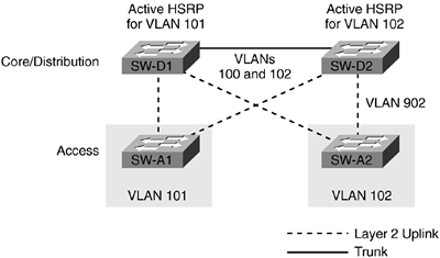
The building block design in Figure 11-2 represents a very simple spanning tree. With this simple design and improvements made using the Rapid Spanning Tree Protocol (RSTP) discussed in Chapter 10, "Implementing and Tuning Spanning Tree," administrators are unlikely to encounter spanning-tree reconvergence problems. In this configuration, HSRP communication occurs directly between the two HSRP peers?SW-D1 and SW-D2?via the trunk between those two switches. As the need to expand the network arises, more building blocks can be added. Figure 11-2 shows VLANs 101 and 102 shaded to indicate that all ports on SW-A1 and SW-A2 will be members of those VLANs. The shading is not a boundary for VLANs 101 and 102. For example, the ports linking SW-A1 and SW-D1 are in VLAN 101, as are the ports linking SW-A1 to SW-D2.
Figure 11-3 illustrates a typical configuration for remote offices where a single router with a T1 or similar speed connection into a Frame Relay network connects to both distribution switches via either 10 Mbps or 10/100 Mbps Ethernet. In this case, the bandwidth bottleneck is not the 10/100 Mbps connection from the distribution switches, but the T1 connection (1.536 Mbps) connection to a home office or other larger location.
Figure 11-3. Typical Remote Office Design
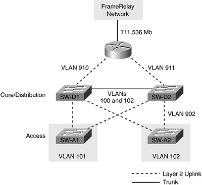
As mentioned in the auto-negotiation section in Chapter 1, "LAN Switching Foundation Technologies," connections between switches and external routers should be manually configured for the appropriate speed and duplex, and not allowed to auto-negotiate. In Figure 11-3, two different VLANs not in use elsewhere in the network are used to connect the switches to the routers. IP subnets with a 30-bit subnet mask like the kind used in the examples in Chapter 7 can be used for these connections, assuming the distribution switches have Layer 3 routing capabilities.
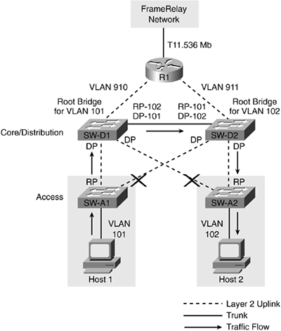
Figure 11-4 shows the converged state of the spanning trees for VLANs 101 and 102 when SW-D1 is the root bridge for VLAN 101 and SW-D2 is the root bridge for VLAN 102. Host 1 is connected to a port on SW-A1 in VLAN 101, and Host 2 is connected to a port on SW-A2 in VLAN 102. Refer to Chapter 10 for a refresher on spanning-tree configuration or on spanning-tree terminology. In Figure 11-4, the port on SW-A1 connecting the switch to SW-D2 is in a blocking state for VLAN 101 because that port is farthest from the root bridge, SW-D1. The same blocking state occurs for VLAN 102 for the port on SW-A2 connecting the switch to SW-D1. When Host 1 on VLAN 101 needs to communicate with Host 2 on VLAN 102, it sends its traffic to its configured default gateway, in this case SW-D1, which is the active HSRP router for VLAN 101. Although SW-D1 has a direct physical connection to VLAN 102 and SW-A2, spanning tree is blocking the connection, and the traffic is forced to take an indirect path through SW-D2 to reach SW-A2 and, ultimately, Host 2.
Figure 11-4. Converged Spanning Tree
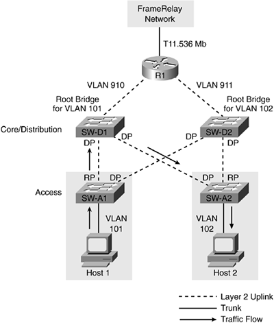
In Figure 11-5, the trunk between SW-D1 and SW-D2 is removed. In this configuration, no loops exist for VLANs 101 and 102, so all ports on SW-D1 and SW-D2 are now forwarding. The arrows indicating traffic flow now show traffic originating on Host 1 being sent directly to SW-A2 by SW-D1, bypassing SW-D2 altogether. This configuration works well when VLANs can be isolated to a single switch, and when connections to the distribution layer are dual-homed. Again, in this scenario, HSRP traffic for switches SW-D1 and SW-D2 flows through the access layer. This type of building block will be used in the "Campus Design" section of this chapter.
Figure 11-5. Removal of Trunk Between SW-D1 and SW-D2
Removing the link between SW-D1 and SW-D2 if other critical devices are single attached to only one of the distribution switches could create potential pitfalls. Figure 11-6 shows the addition of a router R2 with a single attachment to SW-D2, and a server with a single attachment to SW-D2. As long as nothing goes wrong and all the interfaces stay up and running, reaching these new devices from anywhere in the network should not be a problem. Should a connection between an access layer switch and a distribution switch fail, as illustrated in Figure 11-6, communication is disrupted. Single-attached devices also represent a single point of failure in the design should the switch they are attached to fail completely.
Figure 11-6. Single-Attached Router and Server
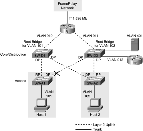
In Figure 11-6, the link between SW-A1 and SW-D2 fails. Because no connection exists between SW-D1 and SW-D2 carrying VLAN 101, and no inter-VLAN routing has been configured, Host 1 cannot communicate with the server in VLAN 401 or R2. It may seem obvious to avoid these kinds of single-attached configurations by dual attaching each router and dual attaching each server, but, often times, the responsibility of overall network administration is segmented into LAN, WAN, and application teams. In some circumstances, servers might get added without the knowledge of the LAN team, and problems do not surface unless a failure of the LAN infrastructure occurs. The next section, "Campus Design," outlines a few options to prevent such problems from occurring.


