Catalyst 3750 (Lord of the Rings) Components and Architecture
One of the newest members of the Catalyst family of switches is the 3750 series, codename Lord of the Rings. The 3750 series is made up of fixed-configuration switches allowing expansion through the interconnection or "stacking" of additional switches into what Cisco terms a cluster rather than through the addition of line modules as with the Catalyst 5000 and 6500 series.
The Catalyst 3750 series offers four models pictured in Figure 3-14 and explained in Table 3-6.
Figure 3-14. Catalyst 3750 Models
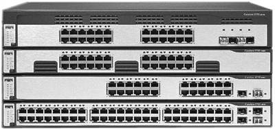
Model | Ports | Modular Uplinks |
|---|---|---|
WS-C3750-24 | 24 10/100 Ethernet | 2 SFP[*] |
WS-C3750-48 | 48 10/100 Ethernet | 4 SFP |
WS-C3750G-24T | 24 10/100/1000 Ethernet | None |
WS-C3750G-24TS | 24 10/100/1000 Ethernet | 4 SFP |
[*] Small Form Factor Pluggable
The Catalyst 3750 series switches use Small Form Factor Pluggable (SFP) uplink ports, which take up less than half the space of a traditional Gigabit Interface Connector (GBIC). The SFPs offer Gigabit Ethernet uplinks using either single or multimode fiber optics. Figure 3-15 shows a SFP and GBIC in a side-by-side comparison.
Figure 3-15. SFP and GBIC
Power and Cooling
The Catalyst 3750 series is a fixed-configuration platform and utilizes an integrated power and cooling system. The only option for power and cooling in the Catalyst 3750 series is the RPS 675, which is a separate power supply module using the same form factor as the switches. The RPS 675 provides redundant power for as many as six switches, providing immediate failover should one internal power supply failure occur.
Stackwise Architecture
Cisco introduced the Stackwise architecture with the Catalyst 3750 series. Stackwise allows the connecting of up to nine Catalyst 3750 series switches via 68-pin Stackwise cables. The logical connections between switches form the common switching fabric and allow the stack to be managed using a single master switch.
The Stackwise architecture differs from other Catalyst architectures in a number of ways. When two or more switches are connected via Stackwise cables, a switch fabric consisting of dual counter-rotating rings is formed, with each ring providing 16 Gbps of bandwidth, resulting in 32 Gbps of total bandwidth. Each ring carries data and is self healing via a loopback protection mechanism that is enabled should a Stackwise cable or individual switch fail.
Figure 3-16 shows an example of the switch fabric formed using the counter-rotating rings when connecting three switches.
Figure 3-16. Functioning 3750 Switch Fabric
Should a link between switches fail, the switches loop back the connection at the point of failure to heal the break. This mechanism will look familiar to anyone with Fiber Distributed Data Interface (FDDI) implementation experience. Figure 3-17 illustrates the locations of loopbacks when a link fails between Switch1 and Switch2.
Figure 3-17. Link Failure Between Switch1 and Switch2
Figure 3-18 illustrates locations of the loopbacks when Switch2 fails completely.
Figure 3-18. Complete Failure of Switch2
Data Flow on the Catalyst 3750
As described earlier in this chapter, the Catalyst 5000 and 6500 series grant bus access to individual line modules. In contrast to the bus architecture of the Catalyst 6500 using a round-robin mechanism to grant access to the shared bus, the Catalyst 3750 series uses a shared token on each ring to determine the order in which port ASICs may transmit data onto the ring. Unlike the centralized intelligence in the Supervisor and shared memory architecture of the Catalyst 4500 series, the Catalyst 3750 distributes the forwarding intelligence and packet buffers onto the port ASICs illustrated in Figure 3-19. The port ASIC is responsible for analyzing the packet, creating a 24-byte header containing the necessary information to make a forwarding decision, and transmitting the header along with the packet onto the ring or fabric. The data flow example in Figure 3-19 demonstrates how packets that are capable of being hardware switched are handled.
Figure 3-19. Data Flow on the Catalyst 3750
The following corresponds to the data flow shown in Figure 3-19:
Host1 is connected to a port on the front of Switch1. The port on Switch1 is connected to a port ASIC on the switch. Host1 transmits a packet to the ingress port on Switch1, destined for Host2 on Switch3.
The port ASIC has intelligence built-in to examine the packet and create the 24-byte header containing the necessary information to make a forward decision.
Each port ASIC has a connection to both rings. The port ASIC will choose a ring for transmission based on the first shared token to arrive. If a shared token arrives on both rings simultaneously, the port ASIC transmits on the least recently used ring. The port ASIC selects a ring and transmits the 24-byte header and the packet data onto a ring.
The destination port ASIC copies the 24-byte header and the packet data from the ring. The header and data are stored in packet buffer memory contained on the port ASIC.
The port ASIC transmits the packet through the egress port on the front of Switch3 to Host2.
The header and packet data continue around the ring until reaching the ingress port ASIC on Switch1. The port ASIC on Switch1 removes the header and data from the ring.


