Catalyst 6000/6500 (Constellation, Constellation+, and Constellation II)
The Catalyst 6000, codename Constellation, was introduced in 1999 and represented a leap forward in switching technology. The Catalyst 6000 increased Ethernet switching bandwidth from 3.6 Gbps to 32 Gbps.
Approximately one year after the introduction of the Catalyst 6000, Cisco introduced the Catalyst 6500 series switches, codename Constellation+. The Catalyst 6500 introduced support for an eventual crossbar switch fabric while providing backward compatibility for modules designed for the 32-Gbps shared bus of the Catalyst 6000. The implementation of support for backward compatibility on the Catalyst 6500 is not much different than the method used on the Catalyst 5500. Both platforms introduced new connections to higher speed crossbar fabrics while providing connections to the legacy shared buses. The 6500 Constellation+ chassis has the electrical connections to support a crossbar switch fabric, but, in 2002, the Switch Fabric Module (SFM) introduced the Constellation II architecture and enabled the 256-Gbps crossbar switch fabric for the Catalyst 6500 platform. The next section discusses each of the Supervisor and Switch Fabric options for these platforms in detail.
Catalyst 6000/6500 Components
Much like the Catalyst 5000/5500 series switches, the Catalyst 6000/6500 is a modular switching platform made up of chassis, supervisors, line modules, and power supply options. The next sections describe each of these Catalyst 6000/6500 components.
Chassis
A wide range of chassis choices are available for the Catalyst 6000/6500. It is important to understand the differences in the various chassis beyond just the number of slots. Table 3-3 describes each Catalyst 6000/6500 chassis model.
Model | Description | Backplane Connections |
|---|---|---|
WS-C6006 | Catalyst 6000 Series 6-slot chassis | 32-Gbps shared bus only |
WS-C6009 | Catalyst 6000 Series 9-slot chassis | 32-Gbps shared bus only |
WS-C6503 | Catalyst 6500 Series 3-slot chassis | 32-Gbps shared bus and 256 Gbps crossbar fabric |
WS-C6506 | Catalyst 6500 Series 6-slot chassis | 32-Gbps shared bus and 256 Gbps crossbar fabric |
WS-C6509 | Catalyst 6500 Series 9-slot chassis | 32-Gbps shared bus and 256-Gbps crossbar fabric |
WS-C6509-NEB | Catalyst 6500 Series 9-slot chassis, NEBS[*] compliant vertical slots | 32-Gbps shared bus and 256-Gbps crossbar fabric |
WS-C6513 | Catalyst 6500 Series 13-slot chassis | 32-Gbps shared bus and 256-Gbps crossbar fabric [**] |
[*] Network Equipment Building Standards (NEBS) is the conformance requirement intended to regulate the quality and reliability of telecom equipment. NEBS was introduced by Bellcore (now Telcordia Technologies), an extension of the seven regional Bell Operating companies (RBOCs).
[**] Requires a Switch Fabric 2 module.
The original Catalyst 6000 series chassis, no longer sold, does not support the crossbar fabric enabled by the SFMs or Supervisor 720. In addition, the SFM and Supervisor 720 can only be installed in designated slots on the Catalyst 6500 series chassis.
Supervisors and Switch Fabrics
Since the introduction of the Catalyst 6000 series switches and the Supervisor I for the Catalyst 6000, three additional Supervisor modules and two SFMs have been introduced:
Supervisor I? The original Supervisor I was introduced with the Catalyst 6000 and implements a shared 32-Gbps bus architecture. It includes two Gigabit Ethernet uplink ports using GBIC connectors and is capable of only Layer 2 switching. The Supervisor I is capable of integrated routing with the optional Multilayer Switch Feature Card version 1 (MSFC1) daughterboard. The MSFC1 is an NPE-200 routing processor not unlike the RSFC for the Catalyst 5500. The Supervisor I does not include a Policy Feature Card (PFC), does not support the MSFC version 2 (MSFC2), and cannot be used with either SFM.
Supervisor IA? In addition to the features of the Supervisor I, the Supervisor IA introduced the PFC, a daughterboard with ASICs enabling multilayer switching, and QoS features at hardware speeds. The PFC on the 6000/6500 is responsible for the same functionality as the EARL on the Catalyst 5000. The Supervisor IA also supports the MSFC2 daughterboard, which is approximately three times faster than the original MSFC at switching packets in software.
Supervisor II? The Supervisor II supports both connections to the 32-Gbps shared bus on the Catalyst 6000/6500 and a connection to the optional crossbar switch fabric enabled via either the Switch Fabric or Switch Fabric II modules. In addition, the Supervisor II includes the PFC version 2 enabling multilayer switching implementing Cisco Express Forwarding (CEF) in hardware. Chapter 6 discusses both MLS and CEF in detail.
Switch Fabric Module (SFM)? The SFM enables a 256-Gbps crossbar switch fabric on the 6500 series switches and is not supported in the Catalyst 6000 chassis. The SFM provides 8 Gbps of bandwidth for each line via direct connections into the switch fabric. The switch fabric contains small input buffers and slightly larger output buffers for each line card connection. The switch fabric utilizes what is termed a "three times overspeed" method of switching frames in and out of the fabric at 24 Gbps. Because frames are being switched between line cards at a much faster rate than they are being sent to the switch fabric, the SFM creates a non-blocking switch fabric with almost all traffic patterns.
Switch Fabric Module II? The SFM version II implemented some internal enhancements over the original SFM including high- and low-priority traffic queues into the switch fabric for each line card, increased available bandwidth from 8 Gbps to 16 Gbps for each line card, and support for the 6513 13-slot chassis.
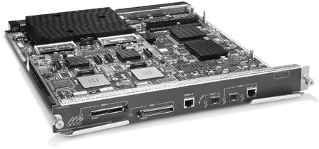
Supervisor 720? A big breakthrough with the Supervisor 720 is the integration of a 720-Gbps switch fabric into the Supervisor itself, freeing a slot normally taken by a separate SFM. The Supervisor 720 includes a new PFC version 3, a new MSFC version 3 (MSFC3), two fiber Gigabit Ethernet uplink ports, and one 10/100/1000 Ethernet RJ-45 uplink port. The Supervisor 720 cannot be used with either the Switch Fabric or Switch Fabric II modules. Figure 3-7 shows a Supervisor 720 module.
Figure 3-7. Catalyst 6500 Supervisor 720
Knowing the version of EARL in use helps determine the forwarding intelligence of each platform. Table 3-4 shows the existing EARL versions. With the introduction of the Catalyst 6000/6500 series switches, EARL functionality is delivered via either a Constellation Advanced Forwarding Engine (CAFE) or a Policy Feature Card (PFC). As of the Supervisor 1A, the PFC replaced the CAFE for all future supervisors. Unlike the Catalyst 5000/5000, Catalyst 6000/6500 documentation rarely refers to an EARL.
Part Number | Model | EARL Version |
|---|---|---|
WS-X6K-SUP1-2GE | Supervisor I | EARL4 (CAFE2) |
WS-X6K-SUP1A-PFC | Supervisor IA | EARL5 (PFC1) |
WS-X6K-S2-PFC2 | Supervisor II | EARL6 (PFC2) |
WS-SUP720 | Supervisor 720 | EARL7 (PFC3) |
Line Modules
Dozens of line cards are available for the Catalyst 6500 platform, ranging from the 24-port WS-X6024-10FL-MT 10 Mb Ethernet multimode fiber-optic module to the 1-port WS-X6502-10GE 10 Gb single-mode fiber-optic module.
Along with the introduction of the SFMs and the Supervisor 720, new switching modules have been introduced to support the higher bandwidth connections into the switch fabrics.
Catalyst 6000/6500 series line cards can be grouped into three major categories:
Classic? Classic line cards have connections only into the 32-Gbps shared bus of the Catalyst 6000 and 6500 series switches.
Fabric enabled? Fabric-enabled line cards have a connection into the legacy 32-Gbps shared bus and a single 8-Gbps connection into the crossbar switch fabric.
Fabric only? Fabric-only line cards do not have a connection into the legacy 32-Gbps shared bus but have two 8-Gbps connections into the crossbar switch fabric.
Distributed switching or forwarding capabilities are possible on some modules via optional Distributed Forward Cards (DFCs). The DFCs are daughterboards that are installable on either fabric-enabled or fabric-only line cards such as the WS-X6516 and the WS-X6816.
Although 256 Gbps of switch bandwidth is available via the SFM and as much as 720 Gbps is available via the Supervisor 720, the Ethernet line cards must rely upon the central switch processors (EARL) in the form of the PFC to make the forwarding decision for each frame or packet. This centralized switching model limits the amount of traffic that can be switched to the processing capabilities of the PFC and the optional routing engine (MSFC). For example, a Catalyst 6500 with a Supervisor II and optional Switch Fabric offers 256 Gbps of switch bandwidth but the PFC2 and MSFC2 on the Supervisor are only capable of forwarding 15 Mpps. The DFCs are essentially a PFC2 and MSFC2 on a daughterboard, capable of making all the same forwarding decisions of the Supervisor at the same speeds. A fabric-enabled line card such as the WS-X6516 with the optional DFC can forward 15 Mpps in addition to the Supervisor's 15 Mpps.
A complete list of available line cards for the Catalyst 6500 can be found by searching the Cisco Systems website at Cisco.com.
Power and Cooling
The type and voltage of power supply is sometimes overlooked. Newer Catalyst switches, especially the 6500 series, offer a range of power supplies with varying power ratings. Depending on the number and type of line cards installed, higher voltage power supplies may be necessary, especially if Ethernet cards with in-line power capabilities are installed. In-line power cards are used to power devices such as IP phones.
For example, Cisco Catalyst 6500 series switch power supplies are available in five power ratings:
950W AC input (Cisco Catalyst 6503 chassis)
1000W AC input
1300W AC and DC input
2500W AC and DC input
4000W AC input
Consult the documentation for the Catalyst 6000/6500 at the Cisco Systems website for detailed power supply specifications and requirements.
In addition to power supplies, fan trays should be considered when configuring a Catalyst switch. Available with the Catalyst 6500 are different models depending on the number of slots in the chassis, and two speeds of fan trays: normal and high speed. Fan tray model and speed are important because a high speed fan tray is required to support the new Supervisor 720 for the Catalyst 6500 series switches.
Catalyst 6000/6500 Architectures
The Catalyst 6000/6500 series switching platforms represent a great leap forward in switching capabilities compared to the Catalyst 5000/5500. This section introduces new terminology specific to the architecture of the Catalyst 6000/6500 and examines data flow used when a SFM is present.
Shared Bus
Much like the Catalyst 5000 series, the Catalyst 6000/6500 series backplane implements an EARL data bus (dBus), an EARL results bus (rBus), and a control bus referred to as the Ethernet Out of Band Channel (EOBC). The EARL designation to describe the buses in this section denotes that the data buses are connected to the EARL switching ASICs on the Supervisor.
EARL Switching or Data Bus (dBus)? The dBus is used to switch frames between line cards. The dBus is 256 bits wide and operates at 62.5 MHz, yielding 16 Gbps of bus bandwidth (32 Gbps full duplex).
Ethernet Out of Band Channel (EOBC)? The EOBC is a control bus that carries configuration information from the Network Management Processor (NMP) to each module and statistical information from each module to the NMP. On the Catalyst 6000/6500, the out of band communications channel runs at 100 Mbps half duplex. The EOBC on the Catalyst 6000/6500 serves the same basic purpose as the management bus (mBus) on the Catalyst 5000.
EARL Results/Index Bus (rBus)? The rBus carries port-select information from the central EARL ASICs to the ports. This information determines which ports forward the packet and which flush it from the buffer.
The process of switching a frame at Layer 2 on a Catalyst 6000/6500 using a shared bus is not much different than on the Catalyst 5000/5500. Greater differences between the platforms are encountered when doing more intelligent switching using information contained in the dBus header. Chapter 6 discusses these differences.
Crossbar Switch Fabrics
Crossbar switch fabrics on the Catalyst 6500 are enabled via the SFM version I or II, or the Supervisor 720.
With the Catalyst 6509, for example, the SFM provides a 16-Gbps (32-Gbps full duplex) connection to each line card. As mentioned previously in the "Supervisors and Switch Fabrics" section, the SFMII is required to support the Catalyst 6513 but because of the number of slots (13), only 8 Gbps is delivered to the first 7 usable slots, and 16 Gbps is provided to the last 5 slots.
Figure 3-8 illustrates the connections from the switch fabric to each module on a Catalyst 6509 switch.
Figure 3-8. Crossbar Switch Fabric on the Catalyst 6509
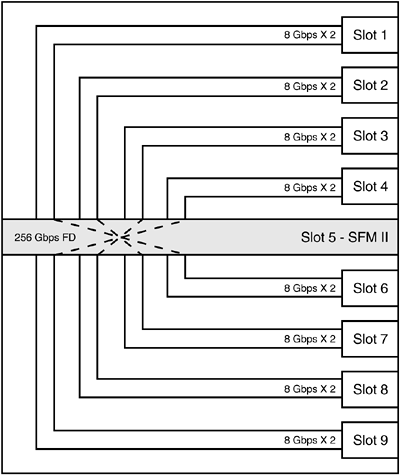
The crossbar switch fabric creates multiple high-speed simultaneous connections between modules.
Catalyst 6500 Switching Modes
All forwarding decisions for all line cards on a Catalyst 6500 utilizing the Supervisor IA are made by the central EARL ASICs on the supervisor (PFC1 or PFC2). This switching mode is called flow through, and in this configuration, each packet is fully transmitted onto the shared bus. This configuration limits the aggregate forwarding capabilities to a maximum of 15 Mpps.
With the introduction of new Supervisors, SFMs, and fabric-enabled line cards, new switching modes enable only a portion of the packet to be transmitted, resulting in higher switching performance.
If the Catalyst 6500 is fabric enabled but contains a mix of classic line cards and fabric-enabled line cards, the switch operates in a mode called truncated. In truncated mode, the classic line cards transmit the entire frame onto the backplane, while fabric-enabled line cards transmit a 96-byte frame (32-byte header + 64-byte data). Because the classic line cards are transmitting full frames, performance in truncated mode is still limited to 15 Mpps.
A Catalyst 6500 utilizing the Supervisor II and SFM, along with fabric-enabled line cards, allows the transmission of only a small header (32 bytes) and subset of the data packet (32 bytes) across the backplane. The resulting 64-byte "compact" frame contains all the information the EARL ASICs on the Supervisor need to make a forwarding decision. This switching mode is called compact and is only enabled when all line cards installed in the switch are fabric enabled. A switch running in compact mode can transmit up to 30 Mpps, twice the speed of a switch operating in flow-through or truncated modes.
Data Flow on the Catalyst 6500 Switch Fabric
Because the high-level operation of the classic shared bus on the Catalyst 6500 and the shared bus on the Catalyst 5000 is similar in many ways, the Catalyst 6500 data flow example uses the optional SFM and fabric-enabled line cards.
Figure 3-9 illustrates at a high level the transmission of a unicast packet from Host1 connected to a Gigabit port on Slot 2 to Host2 connected to a Gigabit port on Slot 3. In the figure, only key ASICs are listed on the supervisor and their locations on the supervisor are not "anatomically correct."
Figure 3-9. Data Flow on the Catalyst 6500 Fabric Enabled
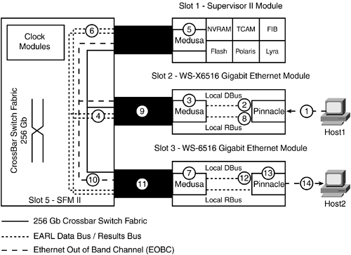
The two WS-X6516 line cards used in Figure 3-9 differ from classic line cards because in addition to their connection to the classic 32-Gbps shared bus, they are fabric enabled via an 8-Gbps connection to the switch fabric. The Medusa ASIC connects the line card to both the classic shared bus and the switch fabric. The data flow example demonstrates how packets that are capable of being hardware switched are handled.
The following explanation corresponds to the data flow shown in Figure 3-9:
The Pinnacle ASIC on Slot 2 sends the frame onto that line card's local data bus (LC-dBus). The line card has a LC-dBus because it is fabric enabled.
The Medusa ASIC and all other Pinnacle ASICs on Slot 2 store the entire data frame.
Because this card is fabric enabled, a 64-byte header is created (Compact Mode). The Medusa in Slot 2 forwards the header to the central EARL data bus (E-dBus).
The Medusa and Forwarding Engine (PFC2) on the Supervisor store the header.
The forwarding engines examine the header and then send the forwarding decision onto the central EARL result bus (E-rBus).
The Medusa ASICs on all line cards see the result, including Slot 3.
The Medusa on Slot 2 forwards the result from the forwarding engine to its local result bus (LC-rBus); all other Medusas (Slot 3) will drop the header.
The Fabric Port of Exit (FPOE) is stored in the result received from the Supervisor Forwarding Engine, and this FPOE is placed in a header that is used to determine where the Switch Fabric sends the frame. The Medusa in Slot 2 will forward the header and the entire data frame to the Switch Fabric.
The Switch Fabric receives the frame and, based on the FPOE, knows to send it to Slot 3.
The Medusa in Slot 3 receives the frame from the Switch Fabric.
The Medusa in Slot 3 forwards the frame to the line card's LC-dBus.
All Gigabit ports on Slot 3 receive the frame.
The Medusa on Slot 3 generates the forwarding result onto the local results bus (LC-rBus).
Local Target Logic (LTL) selects a port on the Pinnacle ASIC connected to Host2 to forward the frame; all other ports on the line card will drop the frame.


