Understanding the MLS Packet Flow
It is critical for the MLS-enabled switch to see the full initial packet flow. In other words, the switch must see the initial packet destined to the inbound router interface, and then, it must also see the packet on the outbound interface of the router. If the switch does not know the outbound interface for the flow of the traffic, it will not have the information to rewrite the MAC at the ASIC level.
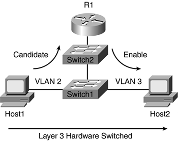
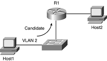
As the packet enters the port destined to another VLAN, the switch will forward the packet to the RSM (see Figure 6-1). This is known as the Candidate packet. Assuming the switch sees the outbound interface, the packet now becomes an Enable packet. The RSM will do a MAC rewrite and forwards the packet out its other interface. The RSM uses fast switching, which is on by default depending on the router code used, to forward the packet. During this process, the switch, MLS-SE, keeps track of this flow. Any other subsequent packets destined to Host2 will be MLS switched by the MLS-SE. At this point, the router will not do any further switching from Host1 to Host2. The router does not even know that the switch is forwarding the packet on its behalf. As a result, debugging or IP accounting commands on the router will not provide any useful information, because the packet is not traversing through the router. The MLS feature not only helps reduce latency in the network, but it also allows for the RSM to do more important functions such as ensuring that it has proper routes and neighbor relationships with its routing peers.
Figure 6-1. Initial Flow Between Two Hosts on Different VLANs
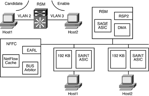
The actual flow of the packet follows. This process is based on a Catalyst 5500 platform. Although the actual implementation might vary slightly depending on the hardware used, the idea is the same:
Host1 sends traffic to Host2 that resides on a separate VLAN. The router's MAC address is used at the frame level.
The packet arrives at the ingress port. The switch stores the packet in the SAINT ASIC and does a FCS check on the packet. If the FCS check is bad, it will drop the packet. Assuming the packet is good, the SAINT will forward the packet to all other ports.
The EARL2, which is on the NFFC card, looks at the 6-byte destination MAC address and informs all other ports via the INDEX bus to keep or flush the packet.
At this point, the EARL2 sees the router interface as the destination MAC address because it periodically receives MLSP hellos from the router.
The EARL2 checks to see if there is an MLS flow for this traffic. If not, it will forward the packet to the router. The packet becomes a Candidate packet now. A partial MLS entry is created.
The SAGE ASIC (higher DMA in place of interface for Ethernet port, but otherwise similar in function to SAINT ASIC) on the RSM is instructed by the EARL2 to accept the packet.
The RSM looks at the packet at Layer 3. It checks its routing table to forward the packet out of the correct interface. In Figure 6-1, it is VLAN 3.
RSM does a MAC rewrite.
RSM forwards the packet out of the VLAN 3 interface.
The switch sees the router MAC address again as the source for the partial flow that was created.
Having seen the router's MAC address for the flow, the switch will complete the MLS entry. The packet is now an Enable packet.
The switch sends Layer 3 flow cache to the rewrite engine. The rewrite engine will be responsible for the header rewrite: Source/Destination MAC, TTL, and CRC.
When the packet for this flow arrives at the SAINT, the EARL2 searches the NetFlow cache, and will forward the packet to a Layer 3 logic that is embedded in the EARL2 ASIC. It instructs all other ports including the RSM to flush the packet from their SAINT and SAGE ports, respectively. Some line cards have one rewrite engine per switching bus on the EARL2, while other line cards have the rewrite engine on the card itself.
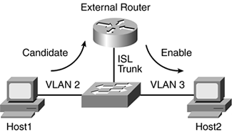
Figure 6-2 uses an external router trunked to the switch with MLS enabled. This example allows for the Layer 3 shortcut to take place because the switch sees the full flow of the traffic.
Figure 6-2. MLS on an External Router
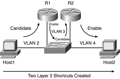
In Figure 6-3, Host2 is two hops away from Host1. The initial packet from Host1 is sent to R1. The XTAG will be that of R1's. The R1 sends the flow back down the ISL trunk to the switch. This causes the first shortcut to be created. The next partial flow is from R1 to R2, where the switch creates an XTAG for R2. When the traffic from R2 is sent back to the switch to Host2, the second full flow is completed. In this setup, the EARL2 will do a look up at the NetFlow cache twice.
Figure 6-3. Two Layer 3 Shortcuts Created
The partial flow is created as the packet from Host1 goes to R1 (see Figure 6-4). Because the switch does not see the packet back from the router, an MLS entry is not created.
Figure 6-4. Shortcut Is Not Created
Both switches will create the Layer 3 shortcut in Figure 6-5. The only caveat here is Switch2's Layer 3 shortcut will time out because all subsequent traffic is handled by Switch1.
Figure 6-5. Multiple Switches Involved
