WLAN Security Methods: Configuration Guidelines and Examples
This section provides configuration guidelines and examples for various security policies discussed in the previous chapters. Configuration capabilities are discussed for the IOS-enabled AP and bridging platforms, but the same features can be enabled using WLSE or the centralized WLAN services command-line interface (CLI) available on Catalyst switching platforms.
At the time of this writing, configuration samples are taken from the 12.2(15)JA IOS release. Most of the configuration samples are provided using IOS CLI commands, but the following section briefly discusses configuration via HTML GUI on the access points/bridges. Note that HTML GUI screen changes are made for each IOS release. Refer to WLAN product documentation on the Cisco website for the latest configuration guidelines.
The configuration examples discussed in this section are relevant for an AP in standalone deployment mode; however, radio interface parameters (such as SSID, VLAN assignment, and encryption parameters) are the same across all three deployment modes. Changes specific to SWAN nonswitching deployment mode are discussed in the section "SWAN Nonswitching Deployment: Configuration Guidelines and Examples" later in this chapter, and SWAN central switching deployment mode is discussed in the section "SWAN Central Switching Deployment: Configuration Guidelines and Examples," also later in this chapter.
Navigating the HTML GUI Configuration Pages
Configuration changes can be made on WLAN AP and bridging platforms using a standard web browser. When the web browser is directed to the IOS-enabled access point/bridge (such as http://10.10.10.21), the user is prompted to log in. Factory defaults for user login are "Cisco" for both user ID and password. You should change this, as discussed in the best practices for secure management section. Figure 12-1 is an HTML GUI configuration screen capture for 12.2(13)JA1 IOS release on access point platforms.
Figure 12-1. HTML GUI Configuration on IOS-Enabled AP
On the Services VLAN page, enable 802.1Q trunking on the AP/bridge by creating the native/management VLAN.
On the Services VLAN page, create user VLANs.
On the Security SSID page, create SSIDs and map them to VLANs. Specify authentication and key management parameters for each SSID.
On the Security Encryption Manager page, specify encryption settings for each VLAN.
On the Security Server Manager page, specify RADIUS server parameters.
On the Wireless Services page, specify the WDS configuration details (if applicable).
The HTML GUI pages provide status and troubleshooting information (errors, logs, and so on) in addition to configuration options. It is recommended that you navigate the HTML GUI screens on the latest IOS release so that you understand the configuration options available on the AP/bridge.
IOS CLI Configuration Examples and Guidelines
This section details IOS CLI configuration for various WLAN security methods discussed in this book. The intention is to increase your knowledge of how various security methods can be enabled for WLAN deployment. Client and RADIUS server configuration details, along with the AP/bridge IOS CLI configuration, are discussed for various security methods. Along with configuration details, troubleshooting tips are provided (where applicable).
Open/No WEP Configuration
The open/no WEP configuration, shown in Example 12-1, is typically used for guest or hotspot services where Layer 2 authentication and data confidentiality are disabled. Guest mode is typically enabled on the SSID to allow the AP to broadcast the guest/hotspot service SSID.
Example 12-1. Open/No WEP Configuration on an IOS-Enabled AP/Bridge
TMELAB-AP1#conf t

Enter configuration commands, one per line. End with CNTL/Z.

TMELAB-AP1(config)#int dot11Radio 0

TMELAB-AP1(config-if)#ssid coffee

TMELAB-AP1(config-if-ssid)#authentication open

! Guest mode enables the AP/Bridge to broadcast SSID information

TMELAB-AP1(config-if-ssid)#guest-mode

TMELAB-AP1(config-if-ssid)#end
Open/with WEP and WPA-PSK Configurations
The open/with WEP (also known as static WEP) configuration, shown in Example 12-2, typically is used on legacy devices that do not support WPA or 802.11i capabilities. These devices are typically found in vertical markets such as retail and manufacturing. One example would be legacy bar-code scanners used in the retail environment for inventory tracking. Typically, guest mode is enabled on the SSID to allow the legacy 802.11 client devices to discover the WLAN network.
Example 12-2. Open/with Static-WEP Configuration on an IOS-Enabled AP/Bridge
TMELAB-AP1(config)#int dot11Radio 0

TMELAB-AP1(config-if)#ssid legacy

TMELAB-AP1(config-if-ssid)#authentication open

TMELAB-AP1(config-if-ssid)#guest-mode

TMELAB-AP1(config-if-ssid)#exit

TMELAB-AP1(config-if)#encryption mode wep mandatory

TMELAB-AP1(config-if)#encryption key 1 size 128bit 0 09876543210987654321098765

transmit-key

TMELAB-AP1(config-if)#end
As discussed in Chapter 6, "Wireless Vulnerabilities," static WEP has several vulnerabilities. Therefore, it is not recommended for deployment in an enterprise, SMB, or vertical environment.
Figure 12-2 illustrates the static WEP configuration required for a Cisco 350 client NIC adapter. It depicts the Cisco Aironet GUI configuration screen shot.
Figure 12-2. Static WEP Configuration on a WLAN Client
Example 12-3. WPA-PSK Configuration on an IOS-Enabled AP/Bridge
TMELAB-AP1(config)#int dot11Radio 0

TMELAB-AP1(config-if)#encryption mode ciphers tkip

TMELAB-AP1(config-if)#ssid msTest2

TMELAB-AP1(config-if-ssid)#authentication open

TMELAB-AP1(config-if-ssid)#authentication key-management wpa

! Specify the pass-phrase for WPA-PSK deployment

TMELAB-AP1(config-if-ssid)#wpa-psk ascii Us3aStrongpAssPhras3

TMELAB-AP1(config-if-ssid)#guest-mode

TMELAB-AP1(config-if-ssid)#end
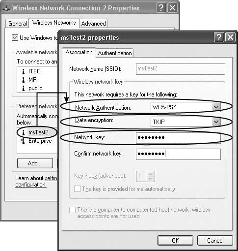
The WPA-PSK passphrase is susceptible to offline dictionary attack; it is recommended that you use a multiple-word passphrase. Figure 12-3 shows the screen capture for a sample WPA-PSK configuration on a Windows XP client.
Figure 12-3. Sample WPA-PSK Client Configuration
WPA-PSK mode is not recommended for deployment in enterprise or vertical environments due to client management issues and its susceptibility to offline dictionary attack. The IT administrator is required to change the WPA-PSK passphrase due to loss or theft of client devices. Thus, client management issues are primarily related to configuring and continuously updating the WLAN clients with the static passphrase required for WPA-PSK deployment.
MAC Address Authentication Configuration
MAC address authentication can be enabled along with open authentication for any security configuration. A sample configuration sequence to enable MAC address authentication is shown in Example 12-4. As shown in the example, a specific user account for MAC address authentication is added on the AP, and the AP is configured to relay the MAC address authentication request to a RADIUS server. The user account shall be created with the MAC address of the WLAN client adapter as the username and the MAC address of the WLAN client as the password to enable MAC address authentication. Typically, MAC address authentication is enabled for legacy 802.11 devices (which do not support 802.11i/WPA) along with the static WEP configuration. If MAC address authentication is enabled, the AP first checks its local database; if the user account is not found, an authentication request can be relayed to a RADIUS server.
Example 12-4. Enabling MAC Address Authentication on an IOS-Enabled AP/Bridge
TMELAB-AP1(config)#int dot11Radio 0

TMELAB-AP1(config-if)#ssid legacy

TMELAB-AP1(config-if-ssid)#authentication open mac-address MacAuth

TMELAB-AP1(config-if-ssid)#end

!

! Adding MAC addresses locally on the WLAN AP/Bridge ---

! Mac address of the WLAN NIC card is used as the username and password

TMELAB-AP1(config)#username 00028a4d80cf password 0 00028a4d80cf

TMELAB-AP1(config)#username 00028a4d80cf autocommand exit

!

! Specify MAC address authentication to a RADIUS server:

TMELAB-AP1(config)#aaa new-model

!Specify Radius Server information

TMELAB-AP1(config)#radius-server host 10.10.10.5 auth-port 1812 acct-port 1813 key

tmelab

! Specify MAC address authentication Servers

TMELAB-AP1(config)#aaa group server radius RadiusMAC

TMELAB-AP1(config-sg-radius)#server 10.10.10.5 auth-port 1812 acct-port 1813

TMELAB-AP1(config-sg-radius)#exit

! Specify rad_mac group of servers to be used for MAC address authentication

TMELAB-AP1(config)#aaa authentication login MacAuth group RadiusMAC

TMELAB-AP1(config)#end
EAP with Dynamic WEP Configuration
EAP with dynamic WEP configuration has been widely implemented as a result of WEP vulnerability (as discussed in Chapter 6). In this deployment, an encryption key per user is dynamically generated and can be periodically rotated. Multiple EAP protocols (as discussed in Chapter 7, "EAP Authentication Protocols for WLANs") can be used, including Cisco LEAP, EAP-TLS, PEAP, and EAP-FAST. Note that both LEAP and EAP Flexible Authentication via Secure Tunneling (EAP-FAST) should be supported using the "network EAP" type on Cisco client adapters. The network EAP type is a Cisco proprietary authentication type (instead of 802.11 open authentication type) used between the WLAN client and the AP. CCX clients are likely to support LEAP or EAP-FAST using the 802.11 open type plus require EAP configuration. Thus, you should enable network EAP and "open+require EAP" on the APs to ensure that all adapters and EAP types are supported.
The configuration required for EAP/802.1x deployment with dynamic WEP is shown in Example 12-5. As shown in the example, both network EAP and open+require EAP are configured for EAP authentication. Also, broadcast key rotation is enabled for the EAP users. In addition to authentication and encryption parameters configuration, RADIUS server configuration is required to relay the authentication request to a specific RADIUS server.
Example 12-5. EAP with Dynamic WEP Configuration on an IOS-Enabled AP
TMELAB-AP1(config)#int dot11Radio 0

TMELAB-AP1(config-if)#ssid Enterprise

! Enable LEAP authentication and specify the LEAP list name "LEAP-AUTH"

TMELAB-AP1(config-if-ssid)#authentication network-eap EAP-AUTH

! Enable EAP authentication methods using "Open+Require EAP"

TMELAB-AP1(config-if-ssid)#authentication open eap EAP-AUTH

! Enable broadcast SSID

TMELAB-AP1(config-if-ssid)#guest-mode

TMELAB-AP1(config-if-ssid)#exit

! There are multiple WEP encryption modes available on Cisco APs. Note that WEP-

optional is Cisco proprietary whereas WEP-Mandatory is Standards based.

TMELAB-AP1(config-if)#encryption mode wep mandatory

! Enable Broadcast Key rotation for every 900 seconds (15 minutes)

TMELAB-AP1(config-if)#broadcast-key change 900

TMELAB-AP1(config-if)#exit

! Configure RADIUS server parameters for EAP authentication

TMELAB-AP1(config)#aaa new-model

! Specify Radius Server information

TMELAB-AP1(config)#radius-server host 10.10.10.5 auth-port 1812 acct-port 1813 key

tmelab

! Specify EAP authentication servers

TMELAB-AP1(config)#aaa group server radius RadiusEAP

! Specify 10.10.10.5 server as an EAP authentication server

TMELAB-AP1(config-sg-radius)#server 10.10.10.5 auth-port 1812 acct-port 1813

TMELAB-AP1(config-sg-radius)#exit

! Specify rad_eap group of servers to be used for EAP authentication

TMELAB-AP1(config)#aaa authentication login EAP-AUTH group RadiusEAP

! Configure miscellaneous RADIUS server parameters

TMELAB-AP1(config)#radius-server attribute 32 include-in-access-req format %h

TMELAB-AP1(config)#radius-server authorization permit missing Service-Type

TMELAB-AP1(config)#radius-server vsa send accounting

TMELAB-AP1(config)#end
Example 12-6. Debug Help
TMELAB-AP1#debug dot11 aaa authenticator process

TMELAB-AP1#debug dot11 aaa authenticator state-machine

!

! An example EAP authentication sequence

TMELAB-AP1#

*Mar  1 00:16:07.447: dot11_auth_dot1x_start: in the dot11_auth_dot1x_start

*Mar 1 00:16:07.447: dot11_auth_dot1x_send_id_req_to_client: sending identity request

for 0007.8592.0c8a

*Mar  1 00:16:07.448: dot11_auth_dot1x_send_id_req_to_client: Started timer

client_timeout 30 seconds

*Mar  1 00:16:07.450: dot11_auth_parse_client_pak: Received EAPOL packet from

0007.8592.0c8a

*Mar  1 00:16:07.450: dot11_auth_dot1x_run_rfsm: Executing

Action(CLIENT_WAIT,EAP_START) for 0007.8592.0c8a

*Mar  1 00:16:07.450: dot11_auth_dot1x_send_id_req_to_client: sending identity request

for 0007.8592.0c8a

*Mar  1 00:16:07.450: dot11_auth_dot1x_send_id_req_to_client: Started timer

client_timeout 30 seconds

*Mar  1 00:16:07.451: dot11_auth_parse_client_pak: Received EAPOL packet from

0007.8592.0c8a

*Mar  1 00:16:07.451: dot11_auth_parse_client_pak: id is not matching req-id: 1resp-

id:2, waiting for response

*Mar  1 00:16:07.456: dot11_auth_parse_client_pak: Received EAPOL packet from

0007.8592.0c8a

*Mar  1 00:16:07.456: dot11_auth_dot1x_run_rfsm: Executing

Action(CLIENT_WAIT,CLIENT_REPLY) for 0007.8592.0c8a

*Mar  1 00:16:07.456: dot11_auth_dot1x_send_response_to_server: Sending client

0007.8592.0c8a data to server

*Mar  1 00:16:07.457: dot11_auth_dot1x_send_response_to_server: Started timer

server_timeout 60 seconds

*Mar  1 00:16:07.468: dot11_auth_dot1x_parse_aaa_resp: Received server response:

GET_CHALLENGE_RESPONSE

*Mar  1 00:16:07.468: dot11_auth_dot1x_parse_aaa_resp: found eap pak in server response

*Mar  1 00:16:07.468: dot11_auth_dot1x_run_rfsm: Executing

Action(SERVER_WAIT,SERVER_REPLY) for 0007.8592.0c8a

*Mar  1 00:16:07.468: dot11_auth_dot1x_send_response_to_client: Forwarding server

message to client 0007.8592.0c8a

*Mar  1 00:16:07.469: dot11_auth_dot1x_send_response_to_client: Started timer

client_timeout 30 seconds

*Mar  1 00:16:07.476: dot11_auth_parse_client_pak: Received EAPOL packet from

0007.8592.0c8a

*Mar  1 00:16:07.476: dot11_auth_dot1x_run_rfsm: Executing

Action(CLIENT_WAIT,CLIENT_REPLY) for 0007.8592.0c8a

*Mar  1 00:16:07.476: dot11_auth_dot1x_send_response_to_server: Sending client

0007.8592.0c8a data to server

*Mar  1 00:16:07.476: dot11_auth_dot1x_send_response_to_server: Started timer

server_timeout 60 seconds

*Mar  1 00:16:07.481: dot11_auth_dot1x_parse_aaa_resp: Received server response:

GET_CHALLENGE_RESPONSE

*Mar  1 00:16:07.481: dot11_auth_dot1x_parse_aaa_resp: found eap pak in server response

*Mar  1 00:16:07.481: dot11_auth_dot1x_run_rfsm: Executing

Action(SERVER_WAIT,SERVER_REPLY) for 0007.8592.0c8a

*Mar  1 00:16:07.482: dot11_auth_dot1x_send_response_to_client: Forwarding server

message to client 0007.8592.0c8a

*Mar  1 00:16:07.482: dot11_auth_dot1x_send_response_to_client: Started timer

client_timeout 30 seconds

*Mar  1 00:16:07.484: dot11_auth_parse_client_pak: Received EAPOL packet from

0007.8592.0c8a

*Mar  1 00:16:07.484: dot11_auth_dot1x_run_rfsm: Executing

Action(CLIENT_WAIT,CLIENT_REPLY) for 0007.8592.0c8a

*Mar  1 00:16:07.485: dot11_auth_dot1x_send_response_to_server: Sending client

0007.8592.0c8a data to server

*Mar  1 00:16:07.485: dot11_auth_dot1x_send_response_to_server: Started timer

server_timeout 60 seconds

*Mar  1 00:16:07.490: dot11_auth_dot1x_parse_aaa_resp: Received server response: PASS

*Mar  1 00:16:07.490: dot11_auth_dot1x_parse_aaa_resp: found session timeout 600 sec

*Mar 1 00:16:07.490: dot11_auth_dot1x_parse_aaa_resp: found eap pak in server response

*Mar 1 00:16:07.491: dot11_auth_dot1x_parse_aaa_resp: found leap session key in server

response

*Mar  1 00:16:07.491: dot11_auth_dot1x_parse_aaa_resp: leap session key length 16

*Mar  1 00:16:07.491: dot11_auth_dot1x_run_rfsm: Executing

Action(SERVER_WAIT,SERVER_PASS) for 0007.8592.0c8a

*Mar  1 00:16:07.491: dot11_auth_dot1x_send_response_to_client: Forwarding server

message to client 0007.8592.0c8a

*Mar  1 00:16:07.492: dot11_auth_dot1x_send_response_to_client: Started timer

client_timeout 30 seconds

*Mar  1 00:16:07.492: %DOT11-6-ASSOC: Interface Dot11Radio0, Station SRISUNDA-W2K

0007.8592.0c8a Associated KEY_MGMT[NONE]
Using the configuration guidance provided in Example 12-5, the EAP with dynamic WEP configuration on the AP/bridge supports LEAP, PEAP, EAP-FAST, EAP-TLS, or any other EAP authentication method. Figure 12-4 shows the LEAP client configuration required on the Cisco Aironet Client Utility (ACU) supplicant using a Cisco 350 PCMCIA client adapter.
Figure 12-4. Sample LEAP Client Configuration
Figure 12-5. Sample PEAP Client Configuration
Figure 12-6. Sample EAP-FAST Client Configuration
Figure 12-7. Sample EAP-TLS Client Configuration
Figure 12-8. PEAP Configuration on a Third-Party EAP Supplicant
Along with client and AP configuration, RADIUS server configuration is required to enable EAP authentication. Specifically, you must add each AP (in standalone mode, also known as non-SWAN mode) as a AAA client on the RADIUS server database, and you must configure appropriate EAP protocol parameters. Alternatively, you can use wildcard addressing (for example, 10.10.10.*) while specifying the AAA client on the RADIUS server to support multiple standalone APs with a single AAA client entry. Figure 12-9 shows how you can add the AP as a AAA client on the Cisco Secure ACS RADIUS server.
Figure 12-9. Basic RADIUS Server Configuration
Figure 12-10. EAP Parameter Configuration on a RADIUS Server
WPA-DOT1x Configuration
As discussed in Chapter 8, "WLAN Encryption and Data Integrity Protocols," several improvements were made in the 802.11i specification to increase the cryptographic strength of RC4 implementation in 802.11 products. This resulted in a data confidentiality and integrity protocol known as TKIP (refer to Chapter 8 for more details). WPA-DOT1x configuration mode enables the network administrator to implement EAP authentication, with WPA-TKIP used for data confidentiality and data integrity. Typically, an enterprise WLAN rollout would use WPA-DOT1x security configuration to provide Layer 2?based user authentication and data confidentiality. Note that you can deploy any EAP protocol (such as LEAP, PEAP, EAP-TLS, or EAP-FAST) along with WPA.
Example 12-7 provides the configuration sequence required to enable WPA on Cisco APs/bridges. As shown in the example, TKIP needs to be configured as the cipher for WPA mandatory deployment mode. Along with the authentication and cipher settings, you must specifiy RADIUS configuration to enable the AP (standalone mode) to relay EAP authentication requests to the RADIUS server.
Example 12-7. WPA-DOT1x Configuration on an IOS-Enabled AP
TMELAB-AP1(config)#int dot11Radio 0

! Enable cipher negotiation and specific data confidentiality protocols that can be

negotiated.

! Note that TKIP, WEP128, and WEP40 are standards based. CKIP, CKIP-CMIC, and CMIC

modes are Cisco proprietary and are known as Cisco TKIP modes.

TMELAB-AP1(config-if)#encryption mode ciphers ?

  ckip       Cisco Per packet key hashing

  ckip-cmic  Cisco Per packet key hashing and MIC (MMH)

  cmic       Cisco MIC (MMH)

  tkip       WPA Temporal Key encryption

  wep128     128 bit key

  wep40      40 bit key

TMELAB-AP1(config-if)#encryption mode ciphers tkip

TMELAB-AP1(config-if)#ssid Enterprise

! Enable LEAP authentication and specify the LEAP list name "EAP-AUTH"

TMELAB-AP1(config-if-ssid)#authentication network-eap EAP-AUTH

! Enable EAP authentication methods using "Open+Require EAP"

TMELAB-AP1(config-if-ssid)#authentication open eap EAP-AUTH

! Enable broadcast SSID

TMELAB-AP1(config-if-ssid)#guest-mode

! Enable WPA authenticated key management

TMELAB-AP1(config-if-ssid)#authentication key-management wpa

TMELAB-AP1(config-if-ssid)#end

!

! Configure RADIUS Server parameters

TMELAB-AP1(config)#aaa new-model

TMELAB-AP1(config)#radius-server host 10.10.10.5 auth-port 1812 acct-port 1813 key 0

tmelab

! Configure RADIUS server group settings

TMELAB-AP1(config)#aaa group server radius EAP-Servers

TMELAB-AP1(config-sg-radius)#server 10.10.10.5 auth-port 1812 acct-port 1813

TMELAB-AP1(config-sg-radius)#exit

! Configure a radius server group for EAP authentication

TMELAB-AP1(config)#aaa authentication login EAP-AUTH group EAP-Servers


! Configure miscellaneous RADIUS server parameters

TMELAB-AP1(config)#radius-server attribute 32 include-in-access-req format %h

TMELAB-AP1(config)#radius-server authorization permit missing Service-Type

TMELAB-AP1(config)#radius-server vsa send accounting

TMELAB-AP1(config)#end
On the WLAN client, you need to configure WPA and a specific EAP protocol to enable the WPA-DOT1x mode. Typically, WPA configuration is independent of the EAP protocol configuration. Thus, follow the recommendations in the previous section as far as configuring LEAP, EAP-TLS, PEAP, or EAP-FAST. Figure 12-11 illustrates WPA configuration for a Cisco EAP-FAST client.
Figure 12-11. Sample EAP-FAST with WPA Client Configuration
Figure 12-12 illustrates the WPA configuration on a Windows XP client.
Figure 12-12. WPA-DOT1x Client Configuration on Windows XP
Example 12-8. Debug Information (WPA-DOT1x)
TMELAB-AP1#debug dot11 aaa authenticator process

TMELAB-AP1#debug dot11 aaa authenticator state-machine

!

! An example WPA-DOT1x authentication sequence (PEAP/with WPA client authentication)

TMELAB-AP1#

*Mar  1 00:50:41.175: dot11_auth_dot1x_start: in the dot11_auth_dot1x_start

*Mar 1 00:50:41.175: dot11_auth_dot1x_send_id_req_to_client: sending identity request

for 0007.8592.3b99

*Mar  1 00:50:41.176: dot11_auth_dot1x_send_id_req_to_client: Started timer

client_timeout 30 seconds

*Mar  1 00:50:41.696: dot11_auth_parse_client_pak: Received EAPOL packet from

0007.8592.3b99

*Mar  1 00:50:41.696: dot11_auth_dot1x_run_rfsm: Executing

Action(CLIENT_WAIT,EAP_START) for 0007.8592.3b99

*Mar  1 00:50:41.696: dot11_auth_dot1x_send_id_req_to_client: sending identity request

for 0007.8592.3b99

*Mar  1 00:50:41.696: dot11_auth_dot1x_send_id_req_to_client: Started timer

client_timeout 30 seconds

*Mar  1 00:50:41.706: dot11_auth_parse_client_pak: Received EAPOL packet from

0007.8592.3b99

*Mar  1 00:50:41.706: dot11_auth_dot1x_run_rfsm: Executing

Action(CLIENT_WAIT,CLIENT_REPLY) for 0007.8592.3b99

*Mar  1 00:50:41.706: dot11_auth_dot1x_send_response_to_server: Sending client

0007.8592.3b99 data to server

*Mar  1 00:50:41.706: dot11_auth_dot1x_send_response_to_server: Started timer

server_timeout 60 seconds

*Mar  1 00:50:41.716: dot11_auth_dot1x_parse_aaa_resp: Received server response:

GET_CHALLENGE_RESPONSE

*Mar 1 00:50:41.716: dot11_auth_dot1x_parse_aaa_resp: found eap pak in server response

*Mar  1 00:50:41.716: dot11_auth_dot1x_run_rfsm: Executing

Action(SERVER_WAIT,SERVER_REPLY) for 0007.8592.3b99

*Mar  1 00:50:41.716: dot11_auth_dot1x_send_response_to_client: Forwarding server

message to client 0007.8592.3b99

*Mar  1 00:50:41.716: dot11_auth_dot1x_send_response_to_client: Started timer

client_timeout 30 seconds

*Mar  1 00:50:41.719: dot11_auth_parse_client_pak: Received EAPOL packet from

0007.8592.3b99

*Mar  1 00:50:41.720: dot11_auth_dot1x_run_rfsm: Executing

Action(CLIENT_WAIT,CLIENT_REPLY) for 0007.8592.3b99

... ..

*Mar  1 00:50:41.915: dot11_auth_dot1x_run_rfsm: Executing

Action(SERVER_WAIT,SERVER_REPLY) for 0007.8592.3b99

*Mar  1 00:50:41.915: dot11_auth_dot1x_send_response_to_client: Forwarding server

message to client 0007.8592.3b99

*Mar  1 00:50:41.915: dot11_auth_dot1x_send_response_to_client: Started timer

client_timeout 30 seconds

*Mar  1 00:50:41.923: dot11_auth_parse_client_pak: Received EAPOL packet from

0007.8592.3b99

*Mar  1 00:50:41.923: dot11_auth_dot1x_run_rfsm: Executing

Action(CLIENT_WAIT,CLIENT_REPLY) for 0007.8592.3b99

*Mar  1 00:50:41.923: dot11_auth_dot1x_send_response_to_server: Sending client

0007.8592.3b99 data to server

*Mar  1 00:50:41.923: dot11_auth_dot1x_send_response_to_server: Started timer

server_timeout 60 seconds

*Mar  1 00:50:41.931: dot11_auth_dot1x_parse_aaa_resp: Received server response: PASS

*Mar  1 00:50:41.931: dot11_auth_dot1x_parse_aaa_resp: found session timeout 600 sec

*Mar 1 00:50:41.931: dot11_auth_dot1x_parse_aaa_resp: found eap pak in server response

*Mar  1 00:50:41.931: dot11_auth_dot1x_parse_aaa_resp: Found AAA_AT_MS_MPPE_SEND_KEY

in server response

*Mar 1 00:50:41.931: dot11_auth_dot1x_parse_aaa_resp: AAA_AT_MS_MPPE_SEND_KEY session

key length 32

*Mar  1 00:50:41.931: dot11_auth_dot1x_parse_aaa_resp: Found AAA_AT_MS_MPPE_RECV_KEY

in server response

*Mar 1 00:50:41.931: dot11_auth_dot1x_parse_aaa_resp: AAA_AT_MS_MPPE_RECV_KEY session

key length 32

*Mar  1 00:50:41.931: dot11_auth_dot1x_run_rfsm: Executing

Action(SERVER_WAIT,SERVER_PASS) for 0007.8592.3b99

*Mar  1 00:50:41.932: dot11_auth_dot1x_send_response_to_client: Forwarding server

message to client 0007.8592.3b99

*Mar  1 00:50:41.932: dot11_auth_dot1x_send_response_to_client: Started timer

client_timeout 30 seconds

*Mar  1 00:50:41.993: %DOT11-6-ASSOC: Interface Dot11Radio0, Station dynamic-

xp0007.8592.3b99 Associated KEY_MGMT[WPA]

TMELAB-AP1#show dot11 associations

802.11 Client Stations on Dot11Radio0:

SSID [Enterprise] :

MAC Address    IP address      Device        Name            Parent         State

0007.8592.3b99 10.10.10.20     350-client    dynamic-xp      self           EAP-Assoc

Others:  (not related to any ssid)
IPSec VPN over WLAN Configuration
As discussed in Chapter 10, "Design Guidelines for Secure WLANs," IPSec VPN deployment over WLAN provides Layer 3?based user authentication and data confidentiality. IPSec VPN over WLAN deployment is an alternative to 802.11i deployment, or you can deploy it in combination with 802.11i to provide both Layer 2? and Layer 3?based user authentication and data confidentiality. Typically, either 802.11i or IPSec VPN over WLAN is deployed in an enterprise or vertical environment. Example 12-9 provides a configuration example for IPSec VPN over WLAN deployment in which policies (filters) are put in place to limit traffic through the access points. 802.11i features are disabled in the configuration example provided; however, if IPSec VPN is implemented with 802.11i, these filters are not necessary but could be implemented optionally by the network administrator.
Example 12-9. AP IOS CLI Configuration for IPSec VPN Inbound and Outbound Filters
interface Dot11Radio0

 no ip address

 ! Apply filters to both in-bound and out-bound traffic on the radio interface

 ip access-group IPSecVPN_InBound in

 ip access-group IPSecVPN_OutBound out

 no ip route-cache

 !

 ssid Enterprise

  authentication open

  guest-mode

 !

 speed basic-1.0 basic-2.0 basic-5.5 basic-11.0

 rts threshold 2312

 station-role root

! Enable Layer 2 filters at the host level on the AP

! Bridge group ACLs are used since radio and Ethernet interfaces are bridged together

! Thus, ACLs would be applied on the BVI interface(s)

 l2-filter bridge-group-acl

 bridge-group 1

 bridge-group 1 subscriber-loop-control

 bridge-group 1 input-type-list 200

 bridge-group 1 output-type-list 200

 bridge-group 1 block-unknown-source

 no bridge-group 1 source-learning

 no bridge-group 1 unicast-flooding

 bridge-group 1 spanning-disabled

!

interface FastEthernet0

 no ip address

 no ip route-cache

 duplex auto

 speed auto

 bridge-group 1

 no bridge-group 1 source-learning

 bridge-group 1 spanning-disabled

!

! Define ACL for inbound IPSec VPN traffic to the AP

ip access-list extended IPSecVPN_InBound

 permit esp any any

 permit icmp any any

 permit udp any any eq domain

 permit udp any any eq bootpc

 permit udp any any eq isakmp

 deny ip any any

!

! Define ACL for outbound VPN traffic to the WLAN clients

ip access-list extended IPSecVPN_OutBound

 permit icmp any any

 permit esp any any

 permit udp any any eq bootps

 permit udp any any eq domain

 permit udp any any eq isakmp

 deny   ip any any

!

! Ethertype filters are used to allow IP (0x0800) and ARP (0x0806) traffic only

access-list 200 permit 0x0806 0x0000

access-list 200 permit 0x0800 0x0000

access-list 200 deny   0x0000 0xFFFF
If 802.11i is disabled for the IPSec VPN over WLAN deployment, the WLAN client should be configured for open/with no WEP.
Along with filters on the APs, IPSec VPN over WLAN policies should be reinforced at the Layer 3 termination point of the IPSec VPN user VLAN (most likely at the distribution layer level), as shown in Example 12-10.
Example 12-10. Recommended ACLs for the VPN User VLAN on the Layer 3 Termination Switch
! This configuration was captured from the Cisco SAFE WLAN implementation lab

! The following are ACLs for the IPSec VLAN 83 mapping to subnet 10.1.83.0/24

! VPN termination gateway is located in the 10.1.50.0/24 subnet

!

! ACL 182 is defined to permit IPSec traffic to the VPN gateway subnet

! ACL 182 is applied to in-bound traffic on the switch port

! That is, ACL is applied to traffic from the AP to the VPN termination gateway

access-list 182 permit esp 10.1.83.0 0.0.0.255 10.1.50.0 0.0.0.255

access-list 182 permit udp 10.1.83.0 0.0.0.255 eq isakmp 10.1.50.0 0.0.0.255 eq isakmp

! Permit full ICMP for troubleshooting

access-list 182 permit icmp 10.1.83.0 0.0.0.255 10.1.50.0 0.0.0.255! Permit DHCP

requests for initial IP assignment for wireless client

access-list 182 permit udp host 0.0.0.0 eq bootpc host 255.255.255.255 eq bootps

access-list 182 permit udp 10.1.83.0 0.0.0.255 eq bootpc host 255.255.255.255 eq bootps

access-list 182 permit udp 10.1.83.0 0.0.0.255 eq bootpc host 10.1.11.50 eq bootps

! Deny all other traffic, don't log Windows file share broadcasts

access-list 182 deny udp 10.1.83.0 0.0.0.255 any eq netbios-ns

access-list 182 deny udp 10.1.83.0 0.0.0.255 any eq netbios-dgm

access-list 182 deny ip any any log

!

!

! ACL 183 is applied to out-bound traffic on the switch port

! ACL 183 allows traffic from the VPN gateway subnet to IPSec VPN user VLAN

access-list 183 permit esp 10.1.50.0 0.0.0.255 10.1.83.0 0.0.0.255

access-list 183 permit udp 10.1.50.0 0.0.0.255 eq isakmp 10.1.83.0 0.0.0.255 eq isakmp

! Permit Full ICMP for troubleshooting

access-list 183 permit icmp 10.1.50.0 0.0.0.255 10.1.83.0 0.0.0.255

! Permit DHCP responses for the initial IP assignment for the wireless client

access-list 183 permit udp host 10.1.11.50 eq bootps host 255.255.255.255 eq bootpc

access-list 183 permit udp host 10.1.11.50 eq bootps 10.1.83.0 0.0.0.255 eq bootpc

! Deny all other traffic

access-list 183 deny ip any any log
Multiple Security Profiles (SSIDs/VLANs) Configuration
Cisco WLAN products support multiple SSIDs (also known as wireless VLANs) and wired VLANs. It is recommended that you deploy multiple VLANs to support multiple security policies on the same WLAN infrastructure. Typically, an SSID is mapped to a wired VLAN and defines a unique security policy. Chapter 13, "WLAN Deployment Examples," provides examples of how multiple SSIDs and VLANs can be used in enterprise and vertical environments. The configuration discussed in this section applies to all three WLAN deployment modes discussed in Chapter 9. However, in SWAN central switching deployment mode, most of the user traffic is not sent over the defined wired VLAN on the AP; rather, it is forwarded via the defined Layer 3 GRE tunnel on the AP.
The native VLAN of the trunk between the AP/bridge and the access (that is, closet) switch serves as the management VLAN for the AP/bridge. It is not allowed to configure management VLAN to be anything other than the native VLAN (mapped to BVI1 interface) of the AP/bridge. IP address identity should be configured on the BVI1 interface to allow management traffic to terminate on the AP/bridge. Note that IP address identity configuration is allowed only for the BVI1 interface on the AP/bridge. Typically, WLAN user traffic is not allowed on the native/management VLAN. (That is, native VLAN is not mapped to an SSID.) Three VLANs are created in Example 12-11. VLAN 10 is defined as the native/management VLAN for the AP, whereas VLANs 11 and 12 are defined as user VLANs. The Example 12-11 configuration sequence applies for standalone AP and SWAN nonswitching deployment modes.
Example 12-11. Multiple SSID and VLAN Configuration on an IOS-Enabled AP
! Create Management/native VLAN on the radio interface

TMELAB-AP1(config)#int dot11Radio 0.10

TMELAB-AP1(config-subif)#encapsulation dot1Q 10 native

! Map the management VLAN to bridge group 1 (BVI1)

TMELAB-AP1(config-subif)#bridge-group 1

TMELAB-AP1(config-subif)#exit

! Create Management/native VLAN on the Ethernet interface

TMELAB-AP1(config)#int fastEthernet 0.10

TMELAB-AP1(config-subif)#encapsulation dot1Q 10 native

! Map the management VLAN to bridge group 1 (BVI1)

TMELAB-AP1(config-subif)#bridge-group 1

TMELAB-AP1(config-subif)#exit

! Create User VLAN-id 11

TMELAB-AP1(config)#int dot11Radio 0.11

TMELAB-AP1(config-subif)#encapsulation dot1Q 11

TMELAB-AP1(config-subif)#bridge-group 11

TMELAB-AP1(config-subif)#exit

TMELAB-AP1(config)#int fastEthernet 0.11

TMELAB-AP1(config-subif)#encapsulation dot1Q 11

TMELAB-AP1(config-subif)#bridge-group 11

TMELAB-AP1(config-subif)#exit

! Create User VLAN-id 12

TMELAB-AP1(config)#int dot11Radio 0.12

TMELAB-AP1(config-subif)#encapsulation dot1Q 12

TMELAB-AP1(config-subif)#bridge-group 12

TMELAB-AP1(config-subif)#exit

TMELAB-AP1(config)#int fastEthernet 0.12

TMELAB-AP1(config-subif)#encapsulation dot1Q 12

TMELAB-AP1(config-subif)#bridge-group 12

TMELAB-AP1(config-subif)#exit

TMELAB-AP1(config)#

! Enable WPA for user VLAN-id 11

TMELAB-AP1(config)#int dot11Radio 0

TMELAB-AP1(config-if)#encryption vlan 11 mode ciphers tkip

TMELAB-AP1(config-if)#broadcast-key vlan 11 change 3600

! Enable static WEP for user VLAN-id 12

TMELAB-AP1(config-if)#encryption vlan 12 mode wep mandatory

TMELAB-AP1(config-if)#encryption vlan 12 key 1 size 128bit 09876543210987654321098765

! Map SSID "Enterprise" to user VLAN-id 11

TMELAB-AP1(config-if)#ssid Enterprise

TMELAB-AP1(config-if-ssid)#vlan 11

! Enable WPA-DOT1x on SSID "Enterprise"

TMELAB-AP1(config-if-ssid)#authentication open eap EAP-AUTH

TMELAB-AP1(config-if-ssid)#authentication key-management wpa

TMELAB-AP1(config-if-ssid)#exit

! Map SSID "Legacy" to user VLAN-id 12

TMELAB-AP1(config-if)#ssid Legacy

TMELAB-AP1(config-if-ssid)#vlan 12

TMELAB-AP1(config-if-ssid)#authentication open

TMELAB-AP1(config-if-ssid)#guest-mode

TMELAB-AP1(config-if-ssid)#exit

!

! Note: Specify RADIUS server parameters as discussed in previous examples
By default, you map each SSID statically to a VLAN, as shown in Example 12-11. However, you can overwrite this SSID-to-VLAN ID mapping and dynamically reassign the user to a different wired VLAN (also known as a dynamic VLAN assignment). Dynamic VLAN assignment is enabled using the 802.1x authentication; the RADIUS server's returned VLAN ID overrides the default VLAN mapping on the AP. Furthermore, dynamic VLAN assignment segments users into user groups and enforces a unique security policy per user group (that is, per wired VLAN). Typically, one SSID is deployed along with multiple wired VLANs per AP to enforce user-group policies across an enterprise network. You can achieve dynamic VLAN assignment on the Cisco WLAN products using the user or user-group IETF tunnel parameters 64 (tunnel type: set to "VLAN"), 65 (tunnel medium type: set to "802"), and 81 (tunnel private group ID: set to VLAN-ID). Figure 12-13 illustrates RADIUS server screen captures for dynamic VLAN assignment configuration using the user or user-group IETF tunnel parameter settings.
Figure 12-13. Dynamic User VLAN Assignment RADIUS Server Configuration
Note that in SWAN central switching deployment mode, you must reassign the WLAN client to a different mGRE tunnel. (Reassigning the client to a different wired VLAN does not have an effect on the user traffic flow.)
You can use the show command shown in Example 12-12 on the AP to verify a client's VLAN assignment.
Example 12-12. AP IOS "show" Command to Verify Client's VLAN/SSID Assignment
TMELAB-AP1#sh dot11 associations all-client

Address           : 0007.8592.3b99            Name: dynamic-xp

IP Address        : 10.12.12.23                  Interface        : Dot11Radio 0

Device            : 350-client                        Software Version: 5.30

State             : EAP-Assoc               Parent           : self

SSID              : Enterprise                VLAN             : 12

Hops to Infra     : 1                           Association Id   : 41

Clients Associated: 0                       Repeaters associated: 0

Key Mgmt type     : NONE               Encryption       : WEP

Current Rate      : 11.0                    Capability       : ShortHdr

Supported Rates   : 1.0 2.0 5.5 11.0

Signal Strength   : -39  dBm           Connected for    : 175 seconds

Signal Quality    : 78 %                   Activity Timeout : 18 seconds

Power-save        : Off                      Last Activity    : 8 seconds ago

Packets Input     : 45                       Packets Output   : 1

Bytes Input       : 8878                     Bytes Output     : 82

Duplicates Rcvd   : 0                       Data Retries     : 0

Decrypt Failed    : 0                        RTS Retries      : 0

MIC Failed        : 0

MIC Missing       : 0
You can map multiple SSIDs to the default VLAN when 802.1Q trunking is disabled on the AP. This is less secure than using multiple VLANs with SSIDs, but it might be useful in a scenario in which 802.1Q VLAN trunking is not supported by the wired infrastructure. Example 12-13 shows the configuration required to enable two SSIDs (one configured for WPA-DOT1x mode and the other configured for WPA-PSK mode) where both SSIDs are mapped to the default VLAN (that is, 802.1Q trunking is disabled). Alternatively, in a retail deployment environment, you could have two SSIDs in which one is configured for EAP/802.1x with dynamic WEP and the other is configured for static WEP mapping to the default VLAN. This would be useful when both EAP/802.1x and legacy clients have to be supported on the same wired VLAN (perhaps due to an ongoing migration from legacy to EAP/802.1x clients). Finally, note that this deployment option limits the capability to enforce unique security policies on the wired network side for specific user groups (or device groups).
Example 12-13. Multiple SSID to Default VLAN Mapping on an IOS-Enabled AP
!

TMELAB-AP1(config)#int dot11Radio 0

! Enable WPA TKIP Cipher

TMELAB-AP1(config-if)#encryption mode ciphers tkip

!

! Enable SSID "Enterprise" and configure WPA-DOT1x mode

TMELAB-AP1(config-if)#ssid Enterprise

TMELAB-AP1(config-if-ssid)#authentication open eap EAP-AUTH

TMELAB-AP1(config-if-ssid)#authentication key-management wpa

!

! Enable SSID "WPA-PSK" and configure WPA-PSK mode

TMELAB-AP1(config-if)#ssid Legacy

TMELAB-AP1(config-if-ssid)#authentication open

TMELAB-AP1(config-if-ssid)#authentication key-management wpa

TMELAB-AP1(config-if-ssid)#wpa-psk ascii AReY0UableT0F0llowAl0ng?PleaseD0s0

TMELAB-AP1(config-if-ssid)#guest-mode

TMELAB-AP1(config-if-ssid)#end

!

! Note: Specify RADIUS server parameters for EAP authentication (as discussed in the

WPA-DOT1x configuration example)


