Hierarchical Topology
To meet your customer's business and communication goals for a corporate network design, you might need to recommend a network topology consisting of many pieces and parts?certainly a daunting venture. This venture can be made easier if you can break things down and develop the design in pieces, or layers. Breaking the design into layers is like cutting a pizza into slices instead of trying to eat the entire pizza at once; you can try designing the entire network as a whole, but tomato sauce might drip down your front.
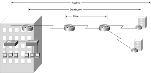
The hierarchical network design model serves to help you develop a network topology in separate layers. Each layer focuses on specific functions, enabling you to choose the right equipment and features for the layer. For example, in Figure 10-9, high-speed WAN routers carry traffic across the enterprise backbone, medium-speed routers connect buildings at each campus, and switches and hubs connect user devices and servers within buildings.
Figure 10-9. Hierarchical Design with Routers (Core), Switches (Distribution), and Hubs (Access)
The hierarchical topology model is made up of the following:
A core layer of high-end routers and switches optimized for network availability and performance.
A distribution layer of routers and switches implementing forwarding decisions.
An access layer connecting users via hubs, bridges, switches, or routers. More about the hierarchical model is discussed in the section "Hierarchical Model" later in this chapter.
Networks that grow without any plan in place tend to develop in an unstructured format. Dr. Peter Welcher, the author of network design and technology articles for Cisco World and other publications, refers to unplanned networks as fur-ball networks.
Dr. Welcher explains the disadvantages of a fur-ball topology by pointing out the problems that too many central processing unit (CPU) adjacencies cause. When network devices communicate with many other devices, the workload required of the CPUs on all the devices can be taxing. In a large flat, or switched, network, for example, broadcast frames are burdensome. A broadcast frame interrupts the CPU on each device within the broadcast domain, and demands processing time on every device, including routers, workstations, and servers.
Using a hierarchical model helps you to minimize network costs because you can buy the appropriate networking devices for each layer of the hierarchy. This in turn avoids spending money on unnecessary features for a layer, not unlike buying a home appliance with features that you are not going to use, such as a microwave with a toothbrush holder. The modular nature of the hierarchical design model also enables you to accurately plan network capacity within each layer of the hierarchy, which means you can reduce wasted bandwidth in your network. That keeps your financial people happy because you are not paying for something you're not using. Network management responsibility and network management systems can also be applied to the different layers of your network to control costs. Again, this is made possible because of the modular architecture of your network.
Network modularity enables you to keep each design element simple and easy to manage. Testing a network design is made easy because there is clear functionality at each layer. Fault isolation is improved because network transition points are easily identified.
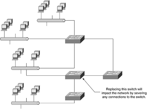
A hierarchical design eases changes in the network environment. A Layer 3 switch helps implement a hierarchical topology. As a network requires changes, such as more users joining the network or a technology refresh/upgrade, the cost of making an upgrade to the network infrastructure is contained to a small section of the network. This is similar to putting pizza toppings on half the pizza rather than the whole. In large, flat network architectures, changes impact a large number of network devices and systems. Replacing one of the network devices in this large network can affect numerous other networks because of the interconnections between each network, as illustrated in Figure 10-10.
Figure 10-10. Replacing a Switch in a Large Network
note
Sometimes taking all or part of the network down to make a change is unavoidable. It is best to let your users know as soon as possible when the network will be unavailable, and for how long. |
Because scalability is often a major goal of any network design, a hierarchical topology is recommended because modularity in the design enables you to create design pieces that can be copied as the network grows, not unlike using a cookie cutter to make the same cookie shape. Because each network module is the same, network expansion is easy to plan, implement, and manage, just as it is easy to use your cookie cutter to make 1 or 100 cookies with the same shape. For example, planning a campus network for a new site might just be a matter of copying an existing campus network design. If it works, why create from scratch?
Hierarchical Model
The cornerstone of any good network is the hierarchical model, which is made up of three pieces, or layers, as illustrated in Figure 10-11.
Figure 10-11. Hierarchical Model (Core, Distribution, and Access Layers)
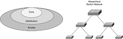
The core layer is a high-speed switching and routing backbone and should be designed to pass network traffic as fast as possible. This layer of the network should not perform any frame or packet manipulation, such as access lists and filtering, which would slow down the switching of traffic and in turn result in less than a "high-speed" environment.
The distribution layer of the network is the demarcation point between the access and core layers and helps define and differentiate the core. The purpose of the distribution layer is to define network boundaries and is the point in the network at which packet manipulation can take place. The distribution layer is where access lists and filtering (based on Layer 2 MAC or Layer 3 network addresses) will take place, providing network security. The distribution layer is also where broadcast domains are defined and traffic between VLANs is routed. If there is any media transition that needs to occur, such as between a 10-Mbps Ethernet and 100-Mbps Fast Ethernet network segment, this transition also happens at the distribution layer.
The access layer is the point at which local end users are allowed into the network. The access layer might also use access lists or filters to further meet the needs of a particular set of users. The access layer is where such functions as bandwidth sharing, filtering on the MAC (Layer 2) address, and microsegmentation can occur.
Layer 3 Switching
Layer 3 switches use the network address to identify where hosts are located on the network. Whereas Layer 2 switches read only the data link layer (MAC) address, Layer 3 switches read both the MAC and network addresses identifying where in the network a host is located from both a logical and physical topology viewpoint.
Switches operating at Layer 3 are smarter than Layer 2 devices because the Layer 3 switch incorporates routing functions calculating the best way to send traffic to its destination. However, although Layer 3 switches are smarter, they may not be as fast if their algorithms, fabric, and processor don't support high speeds. Some Layer 3 switch vendors have specialized application-specific integrated circuits (ASICs,) (pronounced "a-sicks") that enable Layer 3 switching to be as fast as Layer 2 switching. An ASIC is a chip that is custom designed for a specific application rather than a general-purpose chip such as a microprocessor found in a personal computer (PC).


