Components of a LAN
By simple definition, a LAN is two or more devices connected to each other by some type of medium, such as a cable. With the exception of wireless LANs, which are beyond the scope of this book, if there is no cable connection between devices, no connection can occur. These network cables attach to LAN devices via the network interface card (NIC) or network interface port, such as found on a switch.
Cabling
Chapter 3, "Local-Area Networking Introduction," outlined different cabling types. This chapter now details more fully the two most popular types of LAN cabling: twisted pair and fiber optic.
Twisted-Pair Cabling
Twisted-pair cable is a thin-diameter copper wire used for voice and data network cabling. The wires are twisted around each other to minimize interference from other twisted pairs in the cable. Twisted-pair cabling, illustrated in Figure 4-1, enables the use of less bandwidth than required for coaxial cable or optical fiber.
Figure 4-1. Twisted-Pair Cable
Two types of twisted-pair cabling are found in LANs: shielded twisted-pair (STP) and unshielded twisted-pair (UTP).
Shielded Twisted-Pair (STP)
Shielded twisted-pair (STP) is a type of copper wiring in which each of the two copper wires is twisted together and coated with an insulating coating that functions as a ground for the wires. The extra covering in STP wiring protects the transmission line from electromagnetic interference (EMI) leaking into or out of the cable that could result in signal degradation or loss.
STP is used for most Ethernet cabling requirements, especially Fast Ethernet connections, such as 100 megabits per second (Mbps). STP cabling is also used when emission security concerns exist, such as with a classified network (protecting national security information, for instance).
Unshielded Twisted-Pair (UTP)
Unshielded twisted-pair (UTP) is a popular cable type made up of two unshielded wires twisted around each other. Because UTP is not expensive, it is the prevailing choice for LAN and telephone connections. UTP cabling differs from STP in that UTP does not provide the high bandwidth and good protection from EMI that coaxial and fiber-optic cabling provides.
UTP cabling is available in seven standard categories defined by the Telecommunications Industry Association 568 (ANSI/EIA/TIA-568) and are listed in Table 4-1.
Category | Number of Wires | Transmission Rate |
|---|---|---|
1 | Two | Voice (telephone cable) |
2 | Four | Up to 4 Mpbs |
3 | Four | Up to 10 Mbps |
4 | Four | Up to 16 Mbps |
5 | Four | Up to 1 gigabit per second (Gbps) |
5e | Four | Up to 1 Gbps |
6 | Four | Up to 10 Gbps |
The cable category indicates the number of twists per inch. The more twists in the cabling, the more immune the cable from interference, the faster the cable can transmit, and the greater the bandwidth.
Fiber-Optic Cabling
An optical fiber is a thin glass or plastic strand designed for light transmission and capable of transmitting trillions of bits per second. Optical fiber offers many advantages over copper wire because the light pulses carried by fiber are not affected by random radiation in the environment, and its error rate is significantly lower. Fiber enables longer distances to be spanned before the signal has to be regenerated by repeaters, as required for the electrical signal carried by copper wire. Fiber is also more secure than copper because wire taps in the fiber line can be detected.
A fiber-optic cable is essentially a glass or plastic strand encased in a metal and plastic sheath. Light is transmitted across the fiber strands via lasers. To understand how the laser light moves down the strand, imagine shining a flashlight down a poster tube. The tube prevents the light from spreading in all directions; instead, the tube contains the light and provides a path for the light to travel across. The laser is sent from a laser diode at the sending end of the fiber and travels down the strand to the receiver; and no, you cannot set the laser to stun in the laser diode.
Figure 4-2 illustrates the two primary types, or modes, of fiber used in optic transmission: multimode and single mode.
Figure 4-2. Multimode and Single-Mode Fiber
Single-mode fiber is used to span longer distances, and multimode fiber is common for short distances.
Single-mode fiber (SMF) is an optical fiber used for high-speed transmission over long distances. SMF provides a higher-quality cable that allows for a cleaner, stronger signal, and therefore provides more bandwidth than multimode. However, the smaller core of SMF makes it more difficult to align the light source at the receiver.
Multimode fiber (MMF) is an optical fiber with a larger core than single-mode fiber and is the most common fiber used for short distances, such as for LANs. Light can enter the core at different angles, making it easier to transmit light from the source to a broader receiver. This broader scope permits the use of a light emitting diode (LED) rather than the precise laser required by single-mode fiber. This is comparable to the difference between using a flashlight and a laser pointer as a pointing device during a lecture; the flashlight is somewhat broad in its coverage, whereas the laser pointer is more precise.
Cable Termination
Cabling between two devices serves no purpose if there is no way to attach the two together?and although duct tape certainly has its purposes in this world, this is not one of them. Cables, whether copper or fiber optic, are clamped at the ends with a jack connection, known as a registered jack, or RJ.
Several types of RJ connectors are used in networking today, and each type is identified by a number. For example, most telephone handset and wall ports use RJ-11 connectors. Ethernet uses RJ-21 and RJ-45 jack types, and T1 lines use RJ-48.
The RJ-21 (Registered Jack-21) is an Ethernet cable using a 50-pin telco connector on one end. On the other end, the cable branches out to 12 RJ-45 (Registered Jack-45) connectors. The RJ-45 is a connector that holds up to eight wires, as illustrated in Figure 4-3.
Figure 4-3. RJ-45 Plug and Socket (Jack)
These RJ-45 plugs and sockets (jacks) are used in Ethernet and Token Ring devices, as illustrated in Figure 4-4.
Figure 4-4. LAN User Cable Termination Points
The NIC found inside the user's desktop computer or other network device, such as a mail server or network printer, is connected via the network cable to the network interface jack.
Wall Plates and Wall Boxes
Wall plates and wall boxes serve the aesthetic purpose of hiding holes in the wall and visible wires. Wall plates and wall boxes help protect the cable from being pulled out, cut, or damaged. They also help with providing a place to label cables. Further, a box can be organized to centralize multiple services for a user in a single location (for example, phone and data together). Figure 4-5 and Figure 4-6 illustrate a wall plate and a wall box that are often used in LAN implementations.
Figure 4-5. Wall Plates
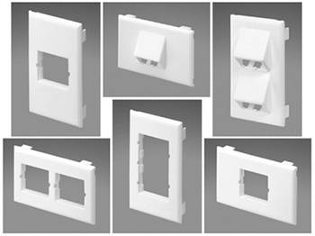
Figure 4-6. Wall Box
The wall plate is mounted onto the wall with an opening for the RJ connection, and a wall box is a freestanding box that can be, but is not always, mounted to a wall. Behind these wall plates and wall boxes is the cabling that runs back to the LAN switch, often sitting in a communications closet somewhere within the building.
Network Interface Card (NIC)
Much as your driveway is an interface to the main road, the network interface card is your interface to the network. With one end of the network cable connected to a port in the wall, the other end needs to connect to a device to complete the circuit. This device is the network interface card, or NIC. NICs are circuit boards that plug into your desktop, laptop, or network servers, such as a web or e-mail server. The NIC controls the sending and receiving of data across the physical Open System Interconnection (OSI) model Layer 1 and data link OSI model Layer 2.


