Radio Interface
1.5 Radio Interface
1.5.1 General Characteristics
Currently, there are several types of networks in the world using the GSM standard, but at different frequencies.
-
The GSM-900 is the most common in Europe and the rest of the world. Its extension is E-GSM.
-
The DCS-1800 operates in the 1,800-MHz band and is used mainly in Europe, usually to cover urban areas. It was also introduced to avoid saturation problems with the GSM-900.
-
The PCS-1900 is used primarily in North America.
-
The GSM-850 is under development in America.
-
The GSM-400 is intended for deployment in Scandinavian countries in the band previously used for the analog Nordic Mobile Telephony (NMT) system.
The system is based on frequency-division duplex (FDD), which means that the uplink (radio link from the mobile to the network-that is, mobile transmit, base receive), and downlink (from the network to the mobile-that is, base transmit, mobile receive) are transmitted on different frequency bands. For instance, in the 900-MHz E-GSM band, the block 880-915 MHz is used for transmission from mobiles to network, and the block 925-960 MHz is used for the transmission from network to mobiles. Table 1.1 gives a summary of uplink and downlink frequency bands for the different GSM systems.
|
Uplink Band |
Downlink Band |
||
|---|---|---|---|
|
GSM-900 |
890-915 MHz |
935-960 MHz |
|
|
E-GSM-900 |
880-915 MHz |
925-960 MHz |
|
|
DCS-1800 |
1,710-1,785 MHz |
1,805-1,880 MHz |
|
|
PCS-1900 |
1,850-1,910 MHz |
1,930-1,990 MHz |
|
|
GSM-400 |
GSM-450 |
450,4-457,6 MHz |
460.4-467.6 MHz |
|
GSM-480 |
478.8-486 MHz |
488.8-496 MHz |
|
|
GSM-850 |
824-849 MHz |
869-894 MHz |
Operators may implement networks that operate on a combination of the frequency bands listed above to support multiband mobile terminals.
There are different ways of sharing the physical resource among all the users in a radio system, and this is called the multiple-access method. The multiple-access scheme defines how simultaneous communications share the GSM radio spectrum. The various multiple-access techniques in use in radio systems are frequency-division multiple access (FDMA), TDMA, and code-division multiple access (CDMA). GSM is based on both FDMA and TDMA techniques (see Figure 1.3).
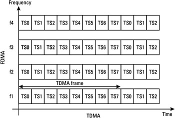 Figure 1.3: TDMA and FDMA.
FDMA consists in dividing the frequency band of the system into several channels. In GSM, each RF channel has a bandwidth of 200 kHz, which is used to convey radio modulated signals, or carriers. Each pair of uplink/ downlink channels is called an absolute radio frequency channel (ARFC) and is assigned an ARFC number (ARFCN). The mapping of each ARFCN on the corresponding carrier frequency is given in [3].
TDMA is the division of the time into intervals: within a frequency channel, the time is divided into time slots. This division allows several users (eight) to be multiplexed on the same carrier frequency, each user being assigned a single time slot. A packet of data information, called a burst, is transmitted during a time slot. The succession of eight time slots is called a TDMA frame, and each time slot belonging to a TDMA frame is identified by a time slot number (TN), from 0 to 7.
1.5.2 Logical Channels
The association of a radio frequency channel and a time slot-the pair ARFCN and TN-uniquely defines a physical channel on both the uplink and the downlink.
On top of the physical channels, logical channels ar mapped to convey the information of voice, data, and signaling. This signaling information is used for setting up a call, or to adapt the link to rapidly changing radio conditions, or to manage handovers, to give a few examples. Logical channels can be seen as pipes, each one used for a different purpose by the higher layers of the system.
Two types of logical channels exist, traffic channels and control channels. Among the control channels, according to their functions, four classes are defined: broadcast, dedicated, common, and associated. A broadcast channel is used by the network (in downlink only) to send general information to the MSs. A channel is said to be dedicated if only one MS can transmit or receive in the ARFCN-TN defining this channel, and common if it carries information for several mobiles. An associated control channel is allocated to one mobile, in addition to a dedicated channel, and carries signaling for the operation of this channel.
The broadcast channels are transmitted on the beacon carrier frequency presented in Section 1.2.7. The purposes of the beacon are:
-
To allow a synchronization in time and frequency of the MSs to the BTS. This synchronization is needed by the MS to access the services of a cell. The frequency and time synchronization procedures that are performed by the mobile are explained in Section 1.5.7.
-
To help the mobile in estimating the quality of the link during a communication, by measurements on the received signal from the BTS it is transmitting to, and from the other BTSs of the geographical area. These measurements are used by the network to determine when a handover is necessary, and to which BTS this handover should apply.
-
To help the mobile in the selection of a cell when it is in idle mode (that is, not in communication, but still synchronized to the system and able to receive an incoming call or to initiate a call). This selection is performed on the basis of the received power measurements made on the adjacent cells' beacon channels.
-
To access the general parameters of the cell needed for the procedures applied by the MS, or general information concerning the cell, such as its identification, the beacon frequencies of the surrounding cells, or the option supported by the cell (services).
To allow these various operations, the logical channels transmitted on the beacon are:
-
The broadcast control channel (BCCH), which continually broadcasts, on the downlink, general information on the cell, including base station identity, frequency allocations, and frequency-hopping sequences. The information is transmitted within system information (SI) blocks, which can be of different types according to the information that is carried out. The frequency with which an SI is retransmitted on the BCCH varies with the type of information.
-
The frequency control channel (FCCH), used by the MS to adjust its local oscillator (LO) to the BTS oscillator, in order to have a frequency synchronization between the MS and the BTS.
-
The synchronization channel (SCH), used by the MS to synchronize in time with the BTS, and to identify the cell.
As listed below, four channels comprise the common control channels (CCCH). Among these, the first three are used for the MS-initiated call or for call paging (notification of an incoming call toward the MS):
-
The random access channel (RACH) is used for the MS access requests to the network, for the establishment of a call, based on a slotted aloha method.
-
The paging channel (PCH) is defined to inform the MS of an incoming call.
-
The access grant channel (AGCH) is used to allocate some physical resource to a mobile for signaling, following a request on the RACH.
-
The cell broadcast channel (CBCH) may be used to broadcast specific news to the mobiles of a cell.
The dedicated control channels are:
-
The stand-alone dedicated control channel (SDCCH), utilized for registration, authentication, call setup, and location updating.
-
The slow associated control channel (SACCH), which carries signaling for the TCH or SDCCH with which it corresponds. The information that is transmitted on this channel concerns the radio link control (RLC), such as the power control on the corresponding TCH or SDCCH, or the time synchronization between the MS and the BTS.
-
The fast associated control channel (FACCH), carries the signaling that must be sent by the network to the MS to notify that a handover is occurring.
The TCHs can be of several types, according to the service that is accessed by the subscribers: voice or data, with various possible data rates.
Table 1.2 summarizes the purpose of the different logical channels. In this table, UL stands for uplink, and DL for downlink.
|
Logical Channel |
Abbreviation |
Uplink/ Downlink |
Task |
|
|---|---|---|---|---|
|
Broadcast channel (BCH) |
Broadcast control channel |
BCCH |
DL |
System Information broadcast |
|
Frequency correction channel |
FCCH |
DL |
Cell frequency synchronization |
|
|
Synchronization channel |
SCH |
DL |
Cell time synchronization and identification |
|
|
Common control channel (CCCH) |
Paging channel |
PCH |
DL |
MS paging |
|
Random access channel |
RACH |
UL |
MS random access |
|
|
Access grant channel |
AGCH |
DL |
Resource allocation |
|
|
Cell broadcast channel |
CBCH |
DL |
Short messages broad cast |
|
|
Dedicated control channel |
Standalone dedicated control channel |
SDCCH |
UL/DL |
General signaling |
|
Slow associated control channel |
SACCH |
UL/DL |
Signaling associated with the TCH |
|
|
Fast associated control channel |
FACCH |
UL/DL |
Handover signaling |
|
|
Traffic channel (TCH) |
Full speech |
TCH/FS |
UL/DL |
Full-rate voice channel |
|
Half rate |
TCH/HS |
UL/DL |
Half-rate voice channel |
|
|
2.4 Kbps, 4.8 Kbps, 9.6 Kbps, and 14.4 Kbps full-rate data channels |
TCH/F2.4 TCH/F4.8 TCH/F9.6 TCH/F14.4 |
UL/DL |
Full-rate data channels |
|
|
2.4-Kbps- and 4.8-Kbps-rate data channels |
TCH/H2.4 TCH/H4.8 |
UL/DL |
Half-rate data channels |
1.5.3 Mapping of Logical Channels onto Physical Channels
1.5.3.1 TDMA Time Structure
The basic time unit is the time slot. Its duration is 576.9 μs = 15/26 ms, or 156.25 symbol periods (a symbol period is 48/13 μs). The piece of information transmitted during a time slot is called a burst. As we saw in Section 1.5.1, the GSM multiple access scheme is TDMA, with eight time slots per carrier. A sequence of eight time slots is called a TDMA frame, and has a duration of 4.615 ms. The time slots of a TDMA frame are numbered from 0 to 7, as shown in Figure 1.4. Note that the beginning and end of TDMA frames in uplink and downlink are shifted in time: Time slot number 0 on the uplink corresponds to time slot 3 in the downlink. This allows some time for the mobile to switch from one frequency to the other.
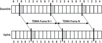
Figure 1.4: Slot numbering within the TDMA frame.
As seen earlier, a physical channel is defined as a sequence of TDMA frames, a time slot number (from 0 to 7) and a frequency. It is bidirectional, with the same TN in uplink and in downlink. In order to support cryptographic mechanisms, a long time-structure has been defined. It is called a hyperframe and has a duration of 3 hours, 28 minutes, 53 seconds, and 760 ms (or 12,533.76 seconds). The TDMA frames are numbered within the hyperframe. The numbering is done with the TDMA frame number (FN) from 0 to 2,715,647.
One hyperframe is subdivided into 2,048 superframes, which have a duration of 6.12 seconds. The superframe is itself subdivided into multi-frames. In GSM, there are two types of multiframes defined, containing 26 or 51 TDMA frames.
The 26 multiframe has a duration of 120 ms, and comprises 26 TDMA frames This multiframe is used to carry TCH, SACCH, and FACCH. The 51 multiframe is made up of 51 TDMA frames. Its duration is 235.4 ms (3,060/13 ms). This multiframe is used to carry BCH, CCCH, and SDCCH (with its associated SACCH). Note that a superframe is composed of twenty-six 51-multiframes, or of fifty-one 26-multiframes. This hierarchical time structure is summarized in Figure 1.5.
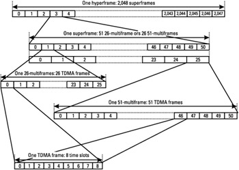
Figure 1.5: Hierarchical structure of a hyperframe.
1.5.3.2 Mapping of the TCH and SACCH on the 26-Multiframe
The TCHs are bidirectional channels mapped onto the 26-multiframe. Two types of channels must be distinguished: full-rate and half-rate channels, and therefore two different mappings of the TCH on the multiframe are possible:
-
A full-rate traffic channel (TCH/FS, for full speech) uses one time slot per TDMA frame, for each frame of the multiframe, except the frames 12 and 25 (see Figure 1.6). The TDMA frame 12 is used to carry the SACCH/FS, and the TDMA frame 25 is an idle frame, which means that no channel is transmitted during this entire TDMA frame.
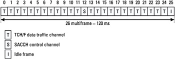
Figure 1.6: Mapping of a TCH/FS and SACCH/FS on the 26-multiframe. -
A half-rate traffic channel (TCH/HS) uses one time slot every two TDMA frames, due to the fact that it carries data from a half-rate voice coder. As shown in Figure 1.7, two half-rate channels can be mapped on the same time slot, one using TDMA frames 0, 2, 4, 6, 8, 10, 13, 15, 17, 19, 21, and 23 and the other one using frames 1, 3, 5, 7, 9, 11, 14, 16, 18, 20, 22, and 24. The SACCH/HS channel associated with the first TCH subchannel is transported on TDMA frame 12, and the SACCH/HS associated with the second subchannel is on time slot 25.
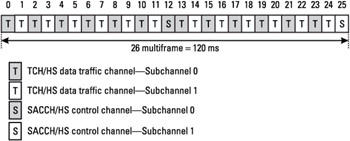
Figure 1.7: Mapping of a TCH/HS and SACCH/HS on the 26-multiframe.
1.5.3.3 Mapping of the FACCH on the 26-Multiframe
The FACCH is associated with a TCH, and is required to support the highspeed signaling needed during call establishment, subscriber authentication, and handover management. The occurrence of the FACCH is not fixed in the multiframe, as it is for the SACCH. Rather, the FACCH occurs on a TDMA frame that is reserved for a TCH. The multiplexing of TCH and FACCH is possible by means of the frame stealing. This means that a speech frame carried over a TCH can be replaced by a FACCH frame. This is signaled to the receiver by means of stealing flags, as described in Section 1.5.4. This principle allows for a fast signaling channel without significant loss on the quality of speech, if it is not performed too often.
1.5.3.4 Mapping of the SDCCH on the 51-Multiframe
The SDCCH is a signaling channel that carries the higher layers of control information. A SACCH is associated with a SDCCH.
Two different multiplexings on the 51 multiframe are possible:
-
SDCCH with SACCH alone. An SDCCH channel is mapped on four TDMA frames of a 51 multiframe. As a result, eight SDCCH channels, dedicated to eight different MSs are mapped onto a 51 multiframe. The TDMA frames not occupied by an SDCCH are used by the eight associated SACCH channels. The mapping of these associated channels is performed on two consecutive 51 multi-frames, as shown in Figure 1.8(b).
-
SDCCH with SACCH multiplexed together with CCCH, BCCH, SCH. and FCCH. This case is described in the next subsection and in Figure 1.8(c).
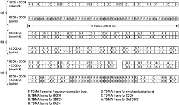
Figure 1.8: Channel associations on the 51-multiframe. (a) BCCH + CCCH, (b) 8 SDCCH/8, and (c) BCCH + CCCH 4 SDCCH/4. (From- [4].)
Note that the frame-stealing concept, used on the TCH to allocate FACCH frames, is not in use in the case of an SDCCH. This is due to the fact that sufficiently fast signaling can be transmitted over an SDCCH to carry on a handover procedure.
1.5.3.5 Mapping of the Broadcast Channels and CCCH on the 51 Multiframe
The broadcast channels and the CCCH (i.e., PCH, RACH, AGCH) are all multiplexed on the 51 multiframe, on the beacon carrier frequency. The FCCH is sent on downlink time slot 0, on the TDMA frames 0, 10, 20, 30, and 40 of the 51 multiframe. The SCH is also mapped on slot 0, in the TDMA frames immediately following an FCCH frame (i.e., frames 1, 11, 21, 31, 41).
The BCCH is associated with time slot 0 as well, in the TDMA frames that are not occupied by the FCCH and the SCH, and can also be mapped on time slots 2, 4, and 6 in some configurations.
The AGCH and PCH are dynamically multiplexed on the multiframe according to the network load. They are mapped on time slot 0, together with the FCCH, SCH, and BCCH, and optionally on time slots 2, 4, and 6 (also possibly used for the BCCH). Note that the BCCH and CCCH are multiplexed dynamically. The exact mapping is conveyed to the MS by means of SI blocks, sent over the BCCH.
One of these broadcast parameters also indicates whether or not the CCCH are combined with SDCCH and SACCH onto the same basic physical channel (the second type of mapping of SDCCH/SACCH presented in Section 1.5.3.4).
The mapping of the RACH channel is simple: every uplink slot corresponding to a downlink FCCH, SCH, BCCH, PCH, and AGCH can be used for a RACH. If the SDCCH and SACCH are multiplexed with the CCCH, the number of available random-access channel blocks are reduced. Figure 1.8(a, c) shows possible configurations with the multiplexing BCCH/ CCCH and BCCH/CCCH/SDCCH/SACCH.
1.5.3.6 Summary of Logical Channel Combinations
The different allowed combinations of logical channels on a physical channel are as follows:
-
TCH/F + FACCH/F + SACCH/TF;
-
TCH/H+ FACCH/H + SACCH/TH;
-
FCCH + SCH + BCCH + CCCH;
-
FCCH + SCH + BCCH + CCCH + SDCCH + SACCH;
-
BCCH + CCCH;
-
SDCCH+ SACCH.
Other logical channels exist for packet-switched services (GPRS, EDGE, or DTM), and will be described later.
1.5.4 Voice Digital Communication Chain
The functions performed by the physical layer during transmission are presented in this section, and the TCH/FS voice channel will be used for the sake of example. The steps of the communication chain, as outlined below, are presented in Figure 1.9.
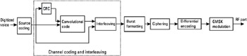
Figure 1.9: The voice transmission chain.
1.5.4.1 Source Coding
First of all, speech must be digitized. On the basis of subjective speech quality and complexity issues, a regular pulse excited-linear predictive coder (RPE-LPC) with a long-term predictor loop was chosen. Basically, information from previous samples, which does not change very quickly, is used to predict the current sample. The coefficients of the linear combination of the previous samples, plus an encoded form of the residual (the difference between the predicted and actual sample), represent the signal. Speech is divided into 20-ms samples, each of which is encoded as 260 bits, giving a total bit rate of 13 Kbps. This is the so-called full-rate speech coding. Several other voice codecs are defined (half rate, enhanced full rate, adaptive multi-rate codecs), but these elements are beyond the scope of this book.
1.5.4.2 Channel Coding
In order to protect the voice against noise, interference, and multipath radio propagation conditions, the encoded speech transmitted over the radio interface is protected from errors. Convolutional encoding and block interleaving are used to achieve this protection. As discussed above, the speech codec produces a 260-bit block for every 20-ms speech sample. From subjective testing, it was found that some bits of this block were more important for perceived speech quality than others. The bits are therefore divided into three classes:
-
Class Ia: 50 bits, most sensitive to bit errors;
-
Class Ib: 132 bits, moderately sensitive to bit errors;
-
Class II: 78 bits, least sensitive to bit errors.
Class Ia bits have a 3-bit cyclic redundancy code added for error detection. If an error is detected, the frame is determined to be incomprehensible, and it is discarded. In such a case it is replaced by a slightly attenuated version of the previous correctly received frame.
These 53 bits, together with the 132 class Ib bits and a 4-bit tail sequence (a total of 189 bits), are input into a 1/2-rate convolutional encoder of constraint length 4. Each input bit is encoded as 2 output bits, based on a combination of the previous 4 input bits. The convolutional encoder thus outputs 378 bits. The 78 remaining class II bits, which are unprotected, are added to these 378 bits. A total of 456 encoded bits are therefore produced for every 20ms speech sample. This represents a bit rate of 22.8 Kbps. In order to protect against burst errors common to the radio interface, each block of 456 bits is interleaved.
1.5.4.3 Interleaving
The 456 coded bits are permutated, and divided into eight blocks of 57 bits, and these blocks are transmitted in eight consecutive bursts, as described in Figure 1.10. Since each burst can carry two 57-bit blocks, each burst carries traffic from two different speech frames. The benefit of doing this is that it provides time diversity. If a sequence of several consecutive bits is corrupted by the degraded propagation conditions (fading, for example) during a given period of time, interleaving ensures that the errors will be randomly distributed over the block of 456 bits. This property is required for a better performance of the decoding algorithm. The decoding of convolutional codes is indeed often performed by the Viterbi algorithm (refer to the case study on this subject in Chapter 4), for which the errors occur in packets. Thus, a random distribution of the corrupted bits over a block at the input of the decoder leads to an increased decoding efficiency, and so to better performance in terms of bit error rate.
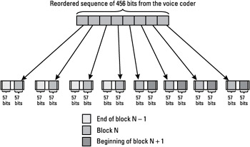
Figure 1.10: Interleaving scheme on the TCH.
1.5.4.4 Burst Formatting
We have seen that the coded bits are interleaved and transmitted over bursts. The format of the burst-carrying TCH traffic, or normal burst (NB), is shown in Figure 1.11. NBs are used on most of the logical channels, except the RACH, SCH, and FCCH. The NB is constituted of two data blocks of 57 bits, carrying the coded voice samples, as described above. The middle of the burst contains the training sequence of 26 bits, known by the receiver, used to estimate the distortion introduced by the radio channel and for time synchronization. At the beginning and at the end of the burst, two sequences of 3 bits, known as the tail bits, all equal to 0, are used. Two bits, one before and one after the training sequence, form the stealing flags (SF). In Section 1.5.3.3 we saw that those bits allow the FACCH and TCH to be multiplexed, with the frame-stealing concept. When a speech frame is stolen for the transmission of a FACCH block, this is signaled by the SF bits. When one stealing bit is equal to one, this means that half of the burst is used for FACCH; otherwise it is used for TCH. An example of the multiplexing of FACCH and TCH is shown in Figure 1.12. Note that a FACCH is transported over eight half bursts. The burst duration is 148 bits, or 546.46 μs, and it is followed by a guard period of 8.25 bits, to allow for the burst ramping up and down between the time slots, as represented in Figure 1.11.
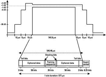
Figure 1.11: Structure of an NB.
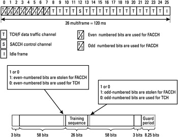
Figure 1.12: Example of frame stealing- multiplexing of a TCH and an FACCH.
1.5.4.5 Ciphering
For security reasons, ciphering is used to modify the data parts of the burst, with a binary addition between a pseudorandom bit sequence and the 114 data bits. The same operation is performed by the receiver for deciphering. The pseudorandom bit sequence is different in the uplink and in the downlink.
1.5.4.6 Differential Encoding
All the bits di of the burst are differentially encoded. The output of the differential encoder is
| (1.1) |
where ⊕ denotes modulo 2 addition.
The result is mapped onto +1 and -1 values, to form the modulating data value αi input to the modulator, as follows:
| (1.2) |
1.5.4.7 GMSK Modulation
The digital signal is modulated onto the analog carrier frequency using Gaussian-filtered minimum shift keying (GMSK), with a symbol period of 48/13 μs (i.e., 270.8333 kHz). This modulation was selected over other modulation schemes as a compromise between spectral efficiency, complexity of the transmitter, power consumption for the MS, and limited out of channels emissions. These radio emissions, outside of the allocated channel, must be strictly controlled so as to limit adjacent channel interference and allow for the coexistence of GSM and the other systems. The spectrum due to the modulation mask requirement is presented in Figure 1.13, along with an ideal GMSK spectrum.
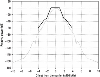
Figure 1.13: Ideal GMSK spectrum and required spectrum mask.
On the receive section, the opposite operations are performed, namely, demodulation, burst deformatting, de-interleaving, channel decoding, and source decoding.
1.5.4.8 Demodulation
Because of the various obstacles in the environment, many reflected signals, each with a different time delay and phase, arrives at the receiver. This is called multipath, and it is time variant, since the terminal is mobile, by definition. To cope with these time-varying propagation conditions, the receiver uses an equalizer. An equalizer is an algorithm that uses the receive sampled symbols to estimate the sequence of bits that was transmitted by the peer entity, by suppressing the intersymbol interference (ISI). Equalization is therefore used to extract the desired signal from the unwanted reflections. To do this, the receiver uses a known sequence of transmitted bits, the training sequence, to estimate the channel impulse response (CIR). This known signal is the 26-bit training sequence transmitted in the middle of every NB. The CIR is then used by the equalizer to retrieve the transmitted symbols. The estimation of the CIR also allows the finest time synchronization of the mobile to the BTS (the mobile can detect and correct a delay of several symbol periods). Note that the actual implementation of the equalizer is not specified in the GSM system, and it is up to the mobile phone or BTS vendor to implement a solution that will achieve the specified receiver performance (see Section 1.5.6.2).
1.5.5 Bursts Format
There are four burst formats the purposes of which are defined as follows:
-
The NB is used to carry information on traffic and control channels, except for RACH, SCH, and FCCH. It contains 114 encrypted symbols and includes a guard time of 8.25 symbol duration (=30,46 μs). A training sequence of 26 symbols is present in the middle of the burst (see Figure 1.11, Section 1.5.4).
-
The frequency correction burst (FB), as shown in Figure 1.14(a), contains a sequence of 142 fixed bits. This sequence is made of alternating ones and zeros (1, 0, 1, 0, ... 1, 0), so that after the differential encoding and GMSK modulation, the RF signal is equivalent to an unmodulated carrier, shifted by 67.7 kHz above the carrier frequency. This characteristic is used to help the mobile synchronize in frequency with the BTS, as explained in Section 1.5.7. The FB is transmitted over the FCCH.
-
The synchronization burst (SB) is needed for time synchronization of the mobile on the SCH. It contains a long training sequence and carries the information of the TDMA FN and base station identity code (BSIC), as can be seen in Figure 1.14(b).
-
The access burst (AB), presented in Figure 1.14(c), is used for random access (or the RACH) and is characterized by a longer guard period (68.25 bit duration or 252 μs), allowing the estimation of the timing advance (TA) by the BTS (see Section 1.5.6.3).
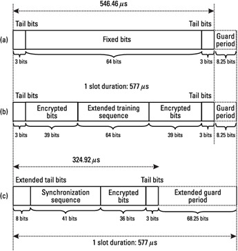
Figure 1.14: The (a) FB, (b) SB, and (c) AB burst structures.
In Figure 1.14, we see a guard period at the end of a burst. During this period, the transmission is attenuated in several steps, as specified by the power-versus-time mask specification (see the example of NB, Figure 1.11).
1.5.6 RF Characteristics
1.5.6.1 Transmission Characteristics
Several classes of mobiles are defined, according to their maximum output power capability, as shown in Table 1.3. In GSM-900, most of the mobiles available on the market are class 4 handheld terminals, while class 2 terminals are used as vehicle-mounted equipment. The class 4 and 5 MSs are denoted as "small MS." In DCS-1800, the typical class is class 1.
|
Power Class |
GSM-400, GSM-900, GSM-850 Nominal Maximum Output Power |
DCS-1800 Nominal Maximum Output Power |
PCS-1900 Nominal Maximum Output Power |
|---|---|---|---|
|
1 |
- |
1W (30 dBm) |
1W(30dBm) |
|
2 |
8W (39 dBm) |
0.25W (24 dBm) |
0.25W (24 dBm) |
|
3 |
5W (37 dBm) |
4W (36 dBm) |
2W (33 dBm) |
|
4 |
2W (33 dBm) | ||
|
5 |
0.8W (29 dBm) |
These output power levels are maximum values, and can be reduced according to the commands that are sent by the network to the MSs. With these network commands, the MS operates at the lowest power level that maintains an acceptable signal quality.
These commands are based on the measurements that are performed by the MS and by the BTS. For instance, with a class 4 MS, the range of transmission can be several kilometers, but if the MS is getting closer to the BTS, it may receive a request from the network to decrease its output power level. This procedure, called power control, improves the performance of the system by reducing the interference caused to the other users. Moreover, it is a means of prolonging the battery life of the mobile. The power level can be stepped up or down in steps of 2 dB from the maximum power (depending on the MS class) down to a minimum of 5 dBm in GSM-400/900/850, and 0 dBm in DCS-1800/PCS-1900. The transmission of power control commands by the BTS is explained in Section 1.5.6.3.
For the BTS transceiver (TRX), the power classes are given in Table 1.4.
|
TRX Power Class |
GSM-400, GSM-900, GSM- 850 Maximum Output Power |
DCS-1800 and PCS-1900 Maximum Output Power |
|---|---|---|
|
1 |
320 (< 640)W |
20(<40)W |
|
2 |
160(<320)W |
10(<20)W |
|
3 |
80(<160)W |
5(<10)W |
|
4 |
40(<80)W |
2.5(<5)W |
|
5 |
20(<40)W | |
|
6 |
10(<20)W | |
|
7 |
5(<10)W | |
|
8 |
2.5(<5)W |
As an option, the BSS can utilize downlink RF power control, with up to 15 steps of power control levels with a step size of 2 dB. Note that this power control on the downlink is not used on the beacon frequency, which is always transmitted with constant output power.
Many other requirements on the transmit section are defined in the GSM specifications, such as the spectrum due to modulation constraint (see Figure 1.13), the modulation accuracy, the transmitter frequency error, and the spurious emissions requirements.
1.5.6.2 Reception Characteristics
Several types of propagation models have been defined, in order to measure the mobile and BTS performances. These models represent several environments:
-
Typical urban (TUx);
-
Rural area (RAx);
-
Hilly terrain (HTx).
In the above definitions, the x stands for the velocity of the mobile, in km/h. The various propagation models are represented by a number of taps, each determined by their time delay and average power. The Rayleigh distributed amplitude of each tap varies according to a Doppler spectrum.
In addition to these multipath fading channels, the static channel was defined. This is a simple single-path constant channel. With this channel, the only perturbation comes from the receiver noise of the measured equipment.
One of the most important receiver performances that is specified is the sensitivity level, which determines the minimum level for which the receiver can demodulate a signal correctly. The sensitivity requirement, in GSM, is specified as an input level, in dBm, for which the measured equipment should reach a certain performance, in terms of bit error rate. For instance, for GSM400/900/850 power classes 4 or 5 mobiles and DCS-1800/PCS-1900 classes 1 or 2 mobiles, the sensitivity level is -102 dBm. For a normal BTS (that is not a micro- or a pico-BTS) the sensitivity level is -104 dBm, for all the frequency bands.
At these levels, different performances, according to both the logical channel and the propagation channel used for the measurement, must be met. Table 1.5 shows an example of performances that are reached at the sensitivity level, for GSM-900 and GSM-850. In this table, BER stands for bit error rate, FER for frame erasure ratio (i.e., incorrect-speech-frames ratio), and RBER for residual BER (defined as the ratio of the number of errors detected over the frames defined as "good" to the number of transmitted bits in the good frames). This table is an example; similar tables exist for the other logical channels and for the different frequency bands. Note that frequency hopping may be used for the sensitivity performance measurements.
|
Propagation Conditions |
||||||
|---|---|---|---|---|---|---|
|
Logical Channel |
Static |
TU (no FH) |
TU50 (ideal FH) |
RA250 (no FH) |
HT100 (no FH) |
|
|
FACCH/H |
(FER) |
0.1% |
6.9% |
6.9% |
5.7% |
10.0% |
|
FACCH/F |
(FER) |
0.1% |
8.0% |
3.8% |
3.4% |
6.3% |
|
SDCCH |
(FER) |
0.1% |
13% |
8% |
8% |
12% |
|
RACH |
(FER) |
0.5% |
13% |
13% |
12% |
13% |
|
SCH |
(FER) |
1% |
16% |
16% |
15% |
16% |
|
TCH/F14.4 |
(BER) |
10.0-5 |
2.5% |
2% |
2% |
5% |
|
TCH/F9.6 |
(BER) |
10.0-5 |
0.5% |
0.4% |
0.1% |
0.7% |
|
TCH/FS |
(FER) |
0.1α% |
6α% |
3α% |
2α% |
7α% |
|
Class Ib |
(RBER) |
0.4/α% |
0.4/α% |
0.3/α% |
0.2/α% |
0.5/α% |
|
Class II |
(RBER) |
2% |
8% |
8% |
7% |
9% |
Note that in this example, the parameter a is defined as 1 ≤ α ≤ 1.6 and allows a tradeoff between the number of erased speech frames (i.e., decoded as wrong, and therefore not transmitted to the voice decoder) and the quality of the nonerased frames.
Another important characteristic of the receiver concerns its performance in the presence of an interferer. This is specified either for a cochannel interference (i.e., an interference situated at the same frequency as the signal of interest) or an adjacent channel interference (situated at 200 or 400 kHz from the carrier of interest). The level of the useful signal is set 20 dB higher than for the sensitivity evaluation, and a GMSK interfering signal is added, either at the same frequency or with an offset of 200 or 400 kHz from the carrier. For the cochannel test, the carrier to interference ratio C/Ic is set to 9 dB. Under these conditions, the performance of Table 1.6 must be met. Again, this table does not contain all the logical channels, and concerns the GSM-900 and GSM-850 only. Similar performance requirements are defined for the other cases.


