Packet Transmission Between MS and SGSN
8.1 Packet Transmission Between MS and SGSN
In the user plane between the MS and SGSN, the IP packets are processed by the SDNCP and LLC protocol layer entities. The SNDCP layer maps the IP protocol characteristics onto the characteristics of the underlying network. IP packets are conveyed in a network protocol data unit (N-PDU) and are encapsulated by the SNDCP layer into an SNDCP PDU (SN PDU) in order to be provided to the LLC layer. The LLC layer provides a reliable logical link between the MS and the SGSN. The LLC PDUs (LL PDUs) are provided by the LLC layer to the underlying layer and are encapsulated into RLC PDUs at air interface and into BSSGP PDUs at Gb interface.
Figure 8.1 illustrates the transport of IP packets between the MS and SGSN.
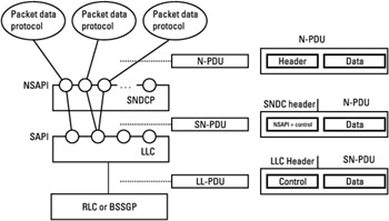 Figure 8.1: IP packets conveyed between MS and SGSN.
8.1.1 LLC Layer
8.1.1.1 General Description
The LLC layer provides logical links between a given MS and its SGSN. Several layer-3 protocols are located above LLC layer in the user plane such as SNDCP and GSMS, and in the control plane such as GMM and SM. The LLC layer operates above RLC layer at air interface and above BSSGP at Gb interface. The layer-three protocols use services provided by the LLC layer at the LLC layer SAP. Figure 8.2 shows the LLC layer structure.
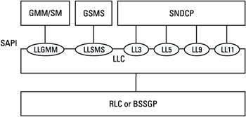
Figure 8.2: LLC-layer structure.
A DLCI identifies a logical link connection. It consists of a service access point identifier (SAPI) and an MS's temporary logical link identifier (TLLI). The SAPI is used to identify the SAP between LLC layer and layer-three protocols above LLC. The TLLI is derived from the P-TMSI, and TLLI assignment is controlled by the GMM layer. TLLI is included in the LLC layer service primitives when an LLC frame is sent or received from lower layers (RLC/MAC layer or BSSGP layer).
The LLC layer supports various transmission modes, acknowledged and unacknowledged modes between the MS and the SGSN. In unacknowledged mode, the layer-three information is sent in numbered unconfirmed information (UI) frames, which are not acknowledged at the LLC layer. In acknowledged mode, the layer-three information is sent in order in numbered information (I) frames.
The GMM PDUs and SM PDUs use the unacknowledged transmission mode for LLC frames in the control plane as well as the SMS PDUs in the user plane. The SNDCP PDUs use either the unacknowledged or the acknowledged transmission mode for LLC frames in the user plane; the LLC transmission mode depends on QoS parameter values negotiated during the PDP context activation procedure.
SAPI1 (LLGMM) is used to identify the SAP of the LLC interface on the MS side and on the SGSN side with GMM/SM entity. SAPI7 (LLSMS) is used to identify the GSMS entity at the LLC-layer level. SAPI3, 5, 7, and 9 are used to identify the SNDCP logical entity at the LLC-layer level. Each SAPI for the SNDCP logical entity is configured differently depending on QoS parameters related to a given PDP context.
Note that a protocol discriminator field present in all GMM/SM messages allows for discrimination of GMM and SM messages sent on SAPI1 (LLGMM).
The LLC layer uses the concepts of link access procedure on the D-channel (LAPD) and is characterized by the following operations:
-
Error detection. The presence of a FCS in LLC frame allows bit errors in the LLC frame header and information fields to be detected.
-
Error recovery and reordering. This mechanism allows for the retransmission of unacknowledged frames in acknowledged transmission mode and the reordering of numbered acknowledged frames in order.
-
Flow control. This is used in acknowledged transmission mode for congestion control of flows between the sender and the receiver when receiver does not have enough time to process the LLC PDUs received.
-
Window management for acknowledgment. This is used to acknowledge a set of LLC frames in acknowledged transmission mode.
-
Asynchronous balanced mode (ABM) operations. Such operations are used to establish or release a logical link in ABM mode in order to send LLC PDUs in an acknowledged transmission mode.
-
XID negotiation. LLC- and SNDCP-layer parameters are negotiated at LLC-layer level between the sender and the receiver.
-
Multiplexing data. A mechanism of SAPI-based LLC-layer contention resolution is used to multiplex several data flows from various upper layers.
Moreover, for data confidentiality, the LLC layer performs the ciphering function on LLC frames whenever the ciphering information (ciphering key Kc and ciphering algorithm) has been assigned to the LLC layer by the GMM layer. Only the information field and the FCS field are ciphered in LLC frames.
8.1.1.2 LLC Format Frame Description
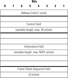
The LLC frame format consists of a frame header (address field and control field), an information field, and an FCS field. The maximum number of octets in the information field (N201) is a LLC-layer parameter negotiated between the peer LLC entities during XID negotiation procedure. Table 8.1 gives the LLC frame format.
|
|
The SAPI is provided in the address field in order to identify the DLCI.
Table 8.2 lists the various LLC frames.
|
LLC Frame Format |
Command |
Response |
Meaning |
|---|---|---|---|
|
Information format frame |
I |
I |
Information |
|
Unacknowledged format frame |
UI |
Unacknowledged Information |
|
|
S Supervisory format frames |
RR |
RR |
Receiver Ready |
|
ACK |
ACK |
Acknowledgment |
|
|
SACK |
SACK |
Selective Acknowledgment |
|
|
RNR |
RNR |
Receiver Not Ready |
|
|
U Unnumbered format frames |
SABM |
Set ABM |
|
|
UA |
Unnumbered Acknowledgment |
||
|
DISC |
Disconnect |
||
|
DM |
Disconnected mode |
||
|
FRMR |
Frame Reject |
||
|
XID |
XID |
Exchange Identification |
|
|
NULL |
Null |
Note that an I frame is considered to be an I + S frame, since each I frame contains supervisory information.
The I + S information format frame contains the sequence number N(S) and the sequence number N(R). The N(S) sequence number indicates the send sequence number of transmitted I frames while the N(R) sequence number indicates that the LLC entity acknowledges all received I frames numbered up to and including N(R) - 1. The S information format frame contains only the transmitter receive sequence number N(R). The UI format frame contains the sequence number N(U), which is the unconfirmed sequence number of transmitted UI frames.
The FCS field contains a 24-bit cyclic redundancy check (CRC) code. For the I frames, the CRC calculation is performed over the entire contents of the frame header and the information field. For the UI frames, the LLC layer offers two protection modes, unprotected mode and protected mode. In protected mode, the CRC is calculated on the entire frame. In unprotected mode, the CRC is calculated on the LLC frame header and on the SNDCP PDU header.
Note that the protection mode is defined during the PDP context activation procedure.
8.1.1.3 Acknowledgment Window Mechanism
The window size for acknowledgment is configured during the XID negotiation procedure and may be up to 255. It means that a sender may send a number of successive LLC frames equal to the window size in acknowledged transmission mode without waiting for the receiver's acknowledgment of the LLC frames already sent.
Note that a small window size implies that the receiver sends acknowledgments often and the sender waits for them often to transmit new LLC frames. A large window size implies a large buffer in the sender side in order to contain all LLC frames sent but not acknowledged by the receiver. The the window size is therefore configured according to the availability of memory in the sender.
In order to manage the windows for transmission and reception, the sender and the receiver use several internal variable states. The sender manages a variable state V(S), which indicates the next in-sequence I frame to be transmitted and a variable state V(A), which indicates the last LLC frame sent and not yet acknowledged by the receiver. The sender numbers each I frame sent to the receiver with a send sequence number N(S), which is set to V(S). The receiver manages a variable state V(R), which indicates the sequence number of the next in-sequence I frame expected to be received. V(R) is incremented by one upon receipt of in-sequence I frame, whose send sequence number N(S) is equal to V(R). All I frames and supervisory frames from the receiver contain the expected send sequence number of the next in-sequence received I frame N(R), which is set equal to V(R) to indicate to the sender that all I frames numbered up to and including N(R) - 1 have been correctly received. The sender updates V(A) by N(R) received from the receiver.
Whenever an LLC entity receives an I + S frame, it analyzes an acknowledgement request bit (A bit) in the control field. If acknowledgement is requested by the sender (A bit set to 1), then the receiver will acknowledge positively or negatively each LLC frame received in an S or I + S frame. The sender will retransmit all I frames not acknowledged positively by the receiver.
The receiver sends an acknowledgment with S or I + S frames under the following form:
-
Acknowledgment of previously received I frames numbered up to and including N(R) - 1 (I frame RR format or I frame RNR format or S frame RR format or S frame RNR format);
-
Acknowledgment of previously received I frames numbered up to and including N(R) - 1, and frame N(R) + 1 (I + S frame ACK format or S frame ACK);
-
Acknowledgment of all previously received I frames numbered up to and including N(R) - 1 and frames indicated by the SACK bitmap (I frame SACK format or S frame SACK).
Note that if the sender receives an I frame ACK format or S frame ACK format, the sender will retransmit only the frame number N(R). If the sender receives an I frame SACK format or S frame SACK format, the sender will retransmit all I frames not acknowledged in the SACK bitmap.
Figure 8.3 gives an example of state variable management.
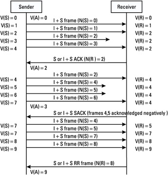
Figure 8.3: Example of state variable management.
8.1.1.4 Data Multiplexing
The LLC layer can manage several logical link connections simultaneously. A logical link entity (LLE) controls one logical link connection. As a logical link connection is identified by a DLCI consisting of SAPI and TLLI as there are different SAPIs, each connection is managed by an LLE.
On frame transmission, each LLE prepares the LLC format on each frame received from the upper layers by completely filling out the address field and the information field of the LLC frame, and partially filling out the control field with the appropriate command or response. The multiplex procedure allows several flows from several LLEs and priorities between the various LLEs to be managed using a SAPI-based LLC-layer contention resolution. The multiplex procedure ends after the control field of the LLC frame is filled. Then it inserts an FCS, performs the ciphering function, and sends the LLC frame to RLC/MAC layer on MS side or to BSSGP layer on SGSN side.
On frame reception, the multiplex procedure, which receives a frame from RLC/MAC on MS side or from BSSGP on SGSN side along with the TLLI parameter, performs the deciphering function, verifies the CRC in the FCS field, and finally analyzes the SAPI in the address field in order to route the LLC frame to the appropriate LLE (identified by DLCI). The LLE extracts the information field from the LLC frame in order to send it to the upper layer across the appropriate SAPI. In acknowledged mode, the LLC guarantees in-order delivery to the upper layers.
Figure 8.4 illustrates the multiplexing procedure.
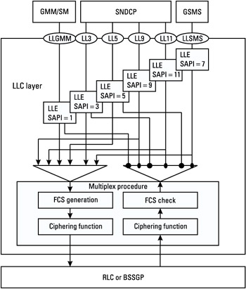
Figure 8.4: Multiplexing procedure.
8.1.1.5 XID Negotiation
This procedure consists in the exchange of some SNDCP- and LLC-layer parameters on SAPIs assigned to a layer-three entity. The negotiated parameters may be at SNDCP level parameters such as header compression and data compression information, and at LLC level parameters such as maximum number of retransmission in acknowledged transmission mode, maximum information field length for I frames or U or UI frames, ciphering input offset value for UI or I frames and retransmission timer value. This procedure may occur at the end of a PDP context activation procedure or at an SGSN change during the establishment of ABM. The XID negotiation procedure is performed by the LLC upon request from the SNDCP layer. The XID negotiation is a one-step procedure. The initiator proposes a set of values for LLC and SNDCP parameters within the allowed values in an I + S frame XID format or an S frame XID format. The receiver may confirm these values or offer other values for these parameters.
8.1.2 SNDCP Layer
The purpose of the SNDCP layer is to multiplex data coming from different PDP sources (e.g., IP, PPP) in order to be sent across the LLC layer in acknowledged or unacknowledged transmission mode. All N-PDUs from the network layer protocols above the SNDCP layer will be carried out in a transparent way through the GPRS network.
In order to improve channel efficiency, the SNDCP entity provides optional compression features on N-PDUs for protocol control information (TCP/IP header compression) and for data. Segmentation and reassembly procedures are performed by the SNDCP entity when the SNDCP PDU exceeds a given length (N201).
8.1.2.1 SNDCP Format Frame Description
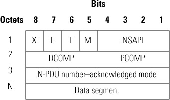
Two different SN-PDUs are defined, the SN-DATA PDU for acknowledged data transfer and SN-UNITDATA PDU for unacknowledged data transfer. Each SN-PDU format consists of a header part and data part.
The SN-DATA PDU format is given in Table 8.3.
|
 |
The SN-UNITDATA PDU format is given in Table 8.4.
|
 |
The fields of the SNDCP PDU header have the following meaning:
-
M: flag that indicates if this is the last N-PDU segment (used for segmentation and reassembly of N-PDUs);
-
T: flag that indicates if this is a SN-DATA PDU or a SN-UNIT-DATA PDU;
-
F: flag that indicates if this is the first segment of an N-PDU (used for segmentation and reassembly of N-PDUs);
-
X: spare bit;
-
DCOMP: data compression identifier if there is data compression (only present for the first segment);
-
PCOMP: protocol control information identifier if there is header compression (only present for the first segment);
-
Segment number: sequence number of SN-UNITDATA PDU (due to the unreliable nature of unacknowledged transmission mode);
-
N-PDU number-acknowledged mode: N-PDU number of an N-PDU sent in acknowledged transmission mode (only present for the first segment);
-
N-PDU number-unacknowledged mode: N-PDU number of an N-PDU sent in unacknowledged transmission mode.
8.1.2.2 Multiplexing of N-PDUs
One PDP may have several PDP contexts identified by an NSAPI. The NSAPI allows the upper source above SNDCP entity to be identified; it is contained in each header of SNDCP PDU (SN-PDU).
When the SNDCP entity receives an N-PDU from the upper layers on a given NSAPI, it encapsulates the N-PDU into a SN-PDU by updating the NSAPI value in the header, and then sends it to the appropriate SAPI of the LLC layer. When the SNDCP entity receives an SN-PDU from the LLC layer on a given SAPI, it deencapsulates the N-PDU in the SN-PDU and routes it to the upper layer according to the NSAPI contained in the SN-PDU.
The NSAPI (11 possible values) and LLC SAPI (4 possible values) are assigned to the SNDCP entity by both the SM entity in the MS and in the SGSN for a given PDP context at the end of the PDP context activation procedure or PDP context modification procedure. An LLC SAPI may be shared by several NSAPIs.
Figure 8.5 shows the multiplexing of N-PDUs.
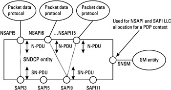
Figure 8.5: Multiplexing of N-PDUs.
8.1.2.3 Establishment and Release of Acknowledged LLC Operation
The SNDCP entity initiates the ABM establishment procedure on a given SAPI if an LLC acknowledged transmission mode is required. At the end of this procedure, the given SAPI is in ABM mode.
The SNDCP entity initiates the ABM release procedure on a given SAPI if there is no NSAPIs requiring an LLC acknowledged transmission mode on this SAPI. It may occur during a PDP context deactivation procedure if the NSAPI was mapped to this SAPI or during a PDP context modification procedure if there is a different mapping between the NSAPI and the SAPI. At the end of this procedure, the given SAPI is in asynchronous disconnected mode (ADM).
Note that the LLC transmission mode is defined during the PDP context activation procedure.
Figure 8.6 shows several scenarios for ABM establishment and release procedures. The first part of the scenario shows an establishment of ABM mode on SAPI3 upon receipt of an indication from the SM entity specifying a PDP context activation with the use of SAPI3 by the allocated NSAPI1. The second part of the scenario shows a release of ABM mode on SAPI3 and an establishment of ABM mode on SAPI5 upon receipt of an indication of a PDP context modification from the SM entity requiring that the previous NSAPI be mapped to SAPI5. The third part of the scenario shows the ABM release procedure on SAPI5 upon receipt of indication of a PDP context deactivation from the SM entity.
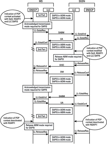
Figure 8.6: Scenarios for ABM establishment and release procedures.
8.1.2.4 Protocol Control Information Compression
The SNDCP entity may propose an optional feature, a protocol control information compression. This is applied on the N-PDU header. There are two compression algorithms supported by the SNDCP layer for protocol control information, the RFC-1144 algorithm (TCP/IP header compression) and the RFC-2507 algorithm (TCP/IP and UDP/IP header compression). A protocol-control-information-compression entity may be shared by several NSAPIs.
The parameters associated with a protocol control information compression are negotiated between protocol-control-information-compression entities within the SNDCP layer in the MS and in SGSN during the XID negotiation procedure.
8.1.2.5 User Data Compression
The SNDCP entity proposes an optional feature for user data compression. The latter may apply on the entire N-PDU for acknowledged and unacknowledged transmission modes and is performed after protocol control information compression if it is used. The only algorithm used for data compression is V.42 bis.
The V.42 bis data compression uses two dictionaries for one direction transmission, one dictionary managed by the data-compression encoder and the other by the data-compression decoder. A dictionary stores strings for use in the encoding and decoding process represented by a set of trees, a hierarchical data structure. A tree consists of nodes; each node corresponds to a character in the alphabet. A node with no parent node is the hierarchically higher level in the tree, called the root node, and represents the first character of a string. A node with no dependent node is the hierarchically lower level in the tree, called the leaf node, and represents the last character of a string. Each node is identified by a unique codeword within the encoder dictionary and the decoder dictionary.
Figure 8.7 shows the tree structure.
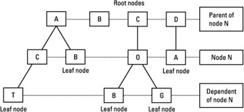
Figure 8.7: Tree structure.
The encoding function performs a string-matching procedure by comparing a sequence of characters (data flow received) with a dictionary entry. In case of matching, the string is sent in compressed mode and is encoded with the codeword associated with it. In case of no matching, the string is sent in transparent mode; the encoder adds the new string in its dictionary with a new node onto a tree by appending a new character to an existing string. A codeword is associated with the next empty dictionary entry; its value is incremented for each new entry. Each time there is a transition of mode of operation from compressed mode to transparent mode or vice versa, the encoder function indicates to the decoder function the transition of encoder state.
The decoding function operates in both compressed and transparent modes. In compressed mode, the decoder retrieves the original sequences of characters identified by codewords in its dictionary. In transparent mode, the decoder adds the new string received in its dictionary by adding a new node onto the tree. A codeword is associated with the string in a manner consistent with the encoding functions.
A V.42 bis compression entity may be shared by several NSAPIs if they use the same dictionary, but there are two separate V.42 bis compression entities for SN PDU in acknowledged and unacknowledged transmission modes. The parameters associated with the V.42 bis data-compression function are negotiated between the data-compression entities within the SNDCP layer in the MS and in SGSN at link establishment via the XID negotiation procedure. These parameters allow for the configuring of the direction of the compression (no compression, or compression from MS to SGSN, or compression from SGSN to MS, or compression for both directions), the maximum number of codewords in the dictionary and the maximum characters in a transparent mode, and the applicable NSAPIs.
8.1.2.6 Segmentation and Reassembly
The SNDCP entity segments an N-PDU into several SN-PDUs to avoid having the SN-PDU transmitted across the SAPI LLC exceed a given length N201. This latter is negotiated by LLC entities during the XID negotiation procedure. There are two N201 values, N201-I value for acknowledged transmission mode and N201-U for unacknowledged transmission mode.
The segmentation reassembly operation uses the flags M and F in order to delimit an N-PDU. The DCOMP and PCOMP will be included in the header only for the first SN-PDU (F bit set to 1). For acknowledged transmission mode, the N-PDU number is also present in the header of the first SN-PDU. For unacknowledged transmission mode, the segment number field is incremented by one for each SN-UNITDATA PDU.
Figure 8.8 shows the segmentation mechanism for acknowledged transmission mode. Figure 8.9 shows the segmentation mechanism for unacknowledged transmission mode.
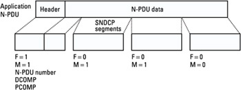
Figure 8.8: Segmentation mechanism for acknowledged transmission mode.
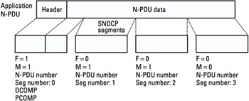
Figure 8.9: Segmentation mechanism for unacknowledged transmission mode.
8.1.3 Case Study: Buffer Management
A buffer management will be put in place for data processing on uplink and on downlink. In order to define a strategy for global buffer management, all functional constraints related to data processing will be identified to determine if the data processing is performed in a new buffer or in the same buffer used by the previous data processing. In one case there is a buffer recopy between each new data processing, while in the other case a simple pointer on the shared buffer is passed. The last solution enables better performance, since there is no time wasted for data recopy from one buffer to another one. In addition, there is an obvious interest in minimizing the number of used buffers for data processing in order to optimize the memory usage, especially for MSs. But as the data transfer processing is performed across several protocol layers from IP layer to RLC/MAC and vice versa, the complexity of data processing algorithms increases if they are all processed in the same buffer. Moreover, the level of interface opening between the protocol layers decreases, since each protocol layer is more dependent on the other.
The buffer management strategy takes into account a priority management when several traffics are processed in the same time. The memory management may define either a memory resource shared by all traffic or a separated memory resource for each traffic.
There is a tradeoff between the various aspects such as performance, optimization of memory use, data processing complexity, and level of interface opening during software design for data transfer processing. This tradeoff is difficult to find because of the transmission chain complexity. In some cases, a simulation system tool may be useful to evaluate the transmission chain complexity, since it enables estimation of the impacts on the transmission chain performance of several configuration parameters, such as buffer length, number of buffers, length of file, number of files, and multiplexing of several traffics in parallel.
8.1.3.1 Examples of Buffer Usage from SNDCP Layer to LLC Layer
A strategy for buffer management from the SNDCP layer to the LLC layer takes into account the various examples of data processing seen in the previous section: protocol control information compression, user data compression, N-PDU segmentation into several SN-PDUs, data multiplexing, addition of LLC headers, addition of CRC, and ciphering of the LLC frame. More functional constraints, such as the following, are also taken into account in this strategy:
-
Waiting for acknowledgment (at LLC or SNDCP layer level);
-
Internal flow control between protocol layers;
-
Segmentation of N-PDU into several SN-PDUs according to N201 length value negotiated by CID negotiation;
-
QoS requirements on each SAPI LLC and on each NSAPI SNDCP.
Two examples of buffer management from the SNDCP layer to the LLC layer are described below, one utilizing a memory recopy and the other without memory recopy. There are other solutions that combine the two solutions.
Example 1: Recopy from SNDCP Layer to LLC Layer
The SNDCP copies the result of IP header compression and of the user data compression in two new buffers. When SNDCP segments one N-PDU into several SN-PDUs, it allocates a new buffer for SN-PDU with its header part and data part by reserving a memory length equal to the length of the LLC frame in order that the LLC layer should append to the received SN-PDU an LLC header and a CRC in the SN-PDU buffer. The LLC copies the result of the ciphering process on the LLC frame into a new buffer.
Figure 8.10 illustrates the buffer recopy mechanism from the SNDCP layer to the LLC layer.
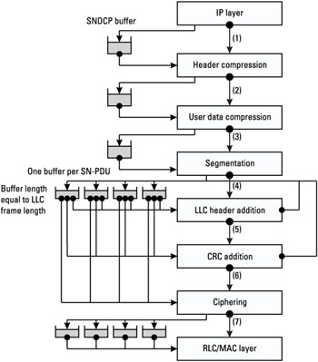
Figure 8.10: Buffer recopy mechanism from SNCP layer to LLC layer.
The implementation of this solution is very simple. It provides for independence between each layer, since data processing is performed by each layer in its own buffer. This solution has an impact on performance in terms of time and on memory consumption due to memory recopy between each data processing layer.
Example 2: No Recopy from SNDCP Layer to LLC Layer
The SNDCP updates in the memory the previous received IP frame with the compressed IP header. No user data compression is performed in this example. When the SNDCP segments one N-PDU into several SN-PDUs, it allocates a new buffer containing the list of header parts associated with each SN-PDU, and each SN-PDU data part is addressed by a pointer in the N-PDU buffer. Next, the SNDCP layer provides a list of two chained pointers to the LLC layer, the first one pointing on the N-PDU buffer at a given place for the SN-PDU data part, the second one pointing on a given place of the SN-PDU header buffer. In order to add an LLC header and CRC to an SN-PDU, the LLC allocates two new buffers, one buffer containing a list of LLC headers associated with each LLC PDU and another one containing a list of CRCs associated with each LLC PDU. Then a list of four chained pointers is provided at the input of the ciphering function, the first one pointing on N-PDU buffer, the second one pointing on SN-PDU header buffer, the third one pointing on LLC header buffer, the fourth one pointing on CRC buffer. Next, memory contents located in the four buffers that are identified by the previous list of four chained pointers are replaced with the result of the ciphering operation.
Figure 8.11 illustrates the second example with no buffer recopy from the SNDCP layer to the LLC layer.
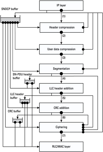
Figure 8.11: No buffer recopy from SNDCP layer to LLC layer.
This solution implies better performances in terms of time due to less memory recopy between each data processing event and less memory consumption, for the same reason as that stated above. With this solution, the layer entities are more dependent from the others. For example, the SNDCP layer must wait for all processing performed by the lower layers such as LLC and RLC to end before preparing a new N-PDU. The implementation of this solution is complex, since all data processing is based on a list of chained pointers. It may be difficult to tune and may be a source of potential bugs. Moreover, it may pose problems with respect to porting this solution from one system to another.
Table 8.5 lists the advantages and the drawbacks with respect to the implementation of the two solutions for the memory usage from the SNDCP layer to the LLC layer.
|
Buffer Recopy |
No Buffer Recopy |
|
|---|---|---|
|
Advantages |
Easy implementation |
Good performance in time |
|
Independence of layers between them |
Low memory consumption |
|
|
Drawbacks |
Bad performance in time |
Complex implementation |
|
High memory consumption |
Dependence of layers between them |
8.1.3.2 Examples of Buffer Usage from LLC Layer to SNDCP Layer
A strategy of buffer management from the LLC layer to the SNDCP layer takes into account the various data processing events such as deciphering of the LLC frame, CRC checking, data demultiplexing, reassembly of several SN-PDUs into N-PDU, user data decompression, and protocol control information decompression. An acknowledgment mechanism and peer-to-peer flow control is taken into account at the LLC-layer level for data receipt in acknowledged mode. In this case, the LLC layer ensures the reordering of the received LLC frames and makes easier the reassemby procedure. While in unacknowledged mode, the SNDCP layer ensures the reordering and the full reassembly procedure, since it is not performed by the LLC layer.
Two examples of buffer management from the LLC layer to the SNDCP layer are described below, one example with a memory recopy and the other without memory recopy.
Example 1: Recopy from LLC to SNDCP
When the LLC layer receives a ciphered LLC PDU from the RLC/MAC layer, it performs the deciphering function and overrides the input buffer with the deciphered frame. If this LLC PDU corresponds to the first segment of N-PDU, then the SNDCP layer allocates a new buffer equal to the maximum length of an N-PDU. The N-PDU buffer is made up of several segments, each segment having a length equal to the data part of SN-PDU. Thus each received LLC PDU is copied in one segment of the N-PDU according to the SN-PDU received number without LLC header, CRC, and SN-PDU header. When all SN-PDUs have been received to be reassembled in one N-PDU, the SNDCP performs the user data decompression and copies the result of these operations into an uncompressed N-PDU buffer read by the IP layer. In this example, no IP header decompression is performed.
Figure 8.12 illustrates the first example with buffer recopy from the LLC layer to the SNDCP layer.
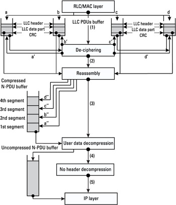
Figure 8.12: Buffer management from LLC layer to SNDCP layer (example 1).
This solution is very simple to implement, being that the layers are independent of the others. But it implies a significant memory consumption, due to the fact that for each new N-PDU, the SNDCP allocates a buffer equal to the maximum length of an N-PDU.
Example 2: No Recopy from LLC to SNDCP
The beginning of the data processing in this example is identical to that of the previous example. When the LLC layer receives a frame carrying an SN-PDU, it provides the SNDCP layer with a pointer on the LLC data part carrying an SN-PDU. If it is the first segment of an N-PDU, the SNDCP layer allocates one buffer containing the list of received pointers on SN-PDUs from the LLC layer. Upon receipt of the last SN-PDU segment, the SNDCP layer reassembles the N-PDU by chaining the list of received pointers. Then the SNDCP layer sends the list of chained pointers on the SN-PDU header to the IP layer. In this example, no user data decompression and no header decompression are performed.
Figure 8.13 illustrates the second example with no buffer recopy from the LLC layer to the SNDCP layer.
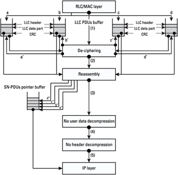
Figure 8.13: Buffer management from LLC layer to SNDCP layer (example 2).
No memory recopy implies less memory consumption and a gain of time between each data processing event. But this solution is hard to implement because it is based on a list of chained pointers for each such event.
The comparison of these two solutions for buffer usage from the LLC layer to the SNDCP layer arrives at the same conclusion as that for buffer usage from the SNDCP layer to the LLC layer. It is provided in Table 8.6.
|
Buffer Recopy |
No Buffer Recopy |
|
|---|---|---|
|
Advantages |
Easy implementation |
Good performance in time |
|
Independence of layers between them |
Low memory consumption |
|
|
Drawbacks |
Bad performance in time |
Complex implementation |
|
High memory consumption |
Dependence of layers between them |


