Protocols
Just as several network protocols are implemented using the OSI model, several network management protocols are implemented using the FCAPS model. The two network management protocols discussed in this chapter are the Simple Network Management Protocol (SNMP) and the Remote Monitoring Protocol (RMON).
Simple Network Management Protocol (SNMP)
SNMP is a popular network management protocol used in today's network environment. SNMP was defined by the Internet Engineering Task Force (IETF) for Transport Control Protocol/Internet Protocol (TCP/IP) networks and is referred to as the "Internet-standard management framework." SNMP defines both a protocol and architecture for managing networks, and the SNMP framework is used when building network management applications or management devices.
SNMP has evolved into three versions; SNMPv1, SNMPv2, and SNMPv3.
SNMPv1 reports only whether a device is up (working) or down (not working).
SNMPv2 includes security and a Remote Monitoring (RMON) Management Information Base (MIB). The RMON MIB provides continuous feedback without having to be queried by the SNMP console.
SNMPv3 provides message-level security. SNMPv3 also includes an MIB for remotely monitoring/managing the configuration parameters for this message-level security.
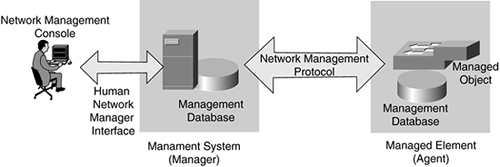
SNMP is based on the manager/agent model consisting of a manager and an agent, a management information database, managed objects, and the network management protocol, as illustrated in Figure 11-10.
Figure 11-10. SNMP Manager and Agent

The SNMP manager provides the interface between the human network manager through a network management console and the management system. The SNMP agent provides the interface between the manager and the network device being managed.
Both the SNMP manager and SNMP agent use the Management Information Base (MIB) and a small set of commands to exchange information. The MIB is organized in a tree structure with individual variables, such as point status or description, being represented as leaves on the branches. (MIBs are further discussed later in this chapter.)
Network management information is exchanged between the SNMP manager and agent through SNMP messages.
SNMP Messages
SNMP uses five messages when communicating between the manager and the agent: GET, GET-NEXT, GET-RESPONSE, SET, and TRAP.
The GET and GET-NEXT messages enable the SNMP manager to request information for a specific variable, such as the status of a switch port: Is the port up or down?
When the GET or GET-NEXT message is received by the SNMP agent, the agent issues a GET-RESPONSE message back to the SNMP manager with the requested information, such as identification of the switch responding with the port status.
The SET message enables the SNMP manager to request that a change be made to a specific variable, such as changing an alarm threshold on a port or device. The SNMP agent responds with a GET-RESPONSE message indicating the change has been made or an error indication as to why the change cannot be made.
The TRAP message enables the agent to alert the SNMP manager of an event, such as a link failure.
The SNMP agent sends information contained in an MIB to the SNMP manager. The MIB is a data structure defining what information is gathered from the device. An MIB might be compared to a job application; only certain information can be asked for and will be provided.
note
In MIB and SNMP messages, a numeric tag called the object identifier (OID) differentiates each variable from another. An OID is made up of a series of numbers separated by decimal points and might look like this: 1.3.5.1.6.4.1.2.7.1. |
SNMP, for all its worth, does have some limitations. SNMP can store a limited amount of information, such as traffic counters or the number of link errors. Another limitation is that SNMP is a polled system, meaning agents respond only to manager requests for information (not including traps, and therefore a sizable amount of network traffic can result from the constant "Is everything okay/Everything is okay" conversations between the SNMP manager and agent.
The RMON protocol was developed to overcome these SNMP limitations and can provide more detailed information.
Remote Monitoring (RMON)
The RMON protocol was developed to overcome the limitations of SNMP. As mentioned, SNMP can store only limited amounts of information (for example, counters for overall traffic and number of errors), and because SNMP is a polled system, additional network traffic is carried, possibly putting more load on the network. RMON provides more detailed information than SNMP and provides for a more simplified data-collection mechanism than SNMP.
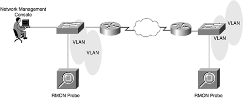
RMON uses a client such as a network management console or a network analyzer, and the RMON client gathers the statistics from one or more RMON agents. These agents can be standalone RMON probes that are located in strategic spots in the network, such as network concentration points, or embedded RMON agents in routers and switches, as illustrated in Figure 11-11.
Figure 11-11. Network Management Console and RMON Client (Probe)

RMON specifies 10 services called RMON groups; 9 groups are for Ethernet, and 1 group is Token Ring. Not all devices have to support all RMON services (because some of the RMON groups require extensive device memory and processor power). Most standalone RMON probes support all 10 services, but embedded RMON might be limited to only a few groups.
Table 11-1 lists the RMON groups.
Technology | RMON Groups | ||
|---|---|---|---|
Group Number | Group Name | Group Description | |
Ethernet | 1 | Statistics | General traffic utilization and error count, including collisions. |
2 | History | Long-term statistics history and is used for baselining. | |
3 | Alarm | Alarms triggered when events occur, similar to SNMP traps, and enable the setting of alarm thresholds. | |
4 | Host | Individual statistics from transmitters (senders) and receivers on the network segment. | |
5 | Host "Top n" | "Top n" of the host statistics, such as the "top 10 hosts reporting errors" or the "top 10 network users"; also known as the "top talkers." | |
6 | Matrix | Packet and error counts for each conversation on the network. | |
7 | Filter | Definition of which packets will be analyzed in statistics or packet-capturing operations. The filter group is required if you are using the capture group. | |
8 | Capture | Capture and storage of packets in the agent prior to transmission to the RMON client. If you are using the capture group you must also use the filter group. | |
9 | Event | Log file of what happened. | |
Token Ring | 10 | Token Ring | Specific Token Ring data, such as beaconing errors on the ring. |
note
Cisco switches support the following RMON groups: statistics group, history group, alarm group, and the event group. |
RMON clients communicate directly to the RMON agent, and RMON collects only data at the OSI Layer 2 (data link) level. If you want information about what the frames are carrying, such as the higher-layer protocols (for example, IP or TCP), you must decode the frames using a protocol analyzer.
RMON2 was developed to provide data on the higher-level protocols, such as IP and Internetwork Packet Exchange (IPX), and through the rest of the OSI model stack, up to and including the application layer (OSI Layer 7). RMON2 provides information on which protocols are being used on the network and the mix between them, standard RMON host and matrix information for the network and applications layers, and a history function that might be used for baselining your network.
RMON is not vital for network testing; however, it makes your life easier and enables you to access the network statistics from wherever you are, such as from the NOC.


