LAN Topologies
In Chapter 3, the implementation of the previous network topologies was discussed. This chapter discusses the more common topologies: the star, ring, and tree topologies. The chapter describes when use of one topology is better than another as well as the role (if any) that switches play in each topology.
There are differences between physical and logical topologies, just as there are differences between physical and logical networks. A physical topology is determined by the cabling that connects the network devices together, whereas a logical topology is determined by the traffic flow across the network.
Star Topology
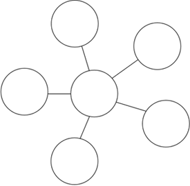
The defining aspect of the star or hub-and-spoke topology is that all network devices are connected to a central point, such as a hub or a switch. The topology resembles a star, as illustrated in Figure 4-7. Star topologies best reflect the difference between a physical and logical topology in that the star topology is wired in a physical star, but your data, such as a print request, moves around the network in a circle.
Figure 4-7. Star or Hub-and-Spoke Topology

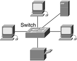
The central point of a star topology plays the role of traffic cop in that it directs traffic to its intended destination rather than to everyone on the network. In a LAN implementation, the traffic cop is often the switch. A star topology with a single switch at its central point might look something like the illustration in Figure 4-8.
Figure 4-8. Single-Switch LAN

This topology might be found in small office/home office (SOHO) networks or small-to medium-sized corporate networks. A switch is central to the LAN, providing a connection between all devices, such as desktop workstations, servers for file sharing or e-mail, or network-attached shared printers.
Ring Topology
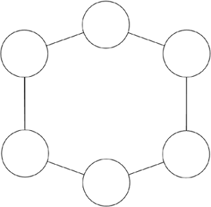
In a physical ring topology, all devices are connected to one another in a closed loop, so that each device is connected to two other devices, one on either side of it. Ring topologies are used in Token Ring and Fiber Distributed Data Interface (FDDI) LANs because of the inherent redundancy in a ring network. For example, if the connection on one side of your machine goes down, the connection on the other side of your machine remains up so you are still connected to network resources.
Figure 4-9. Ring Topology

Ring topologies do not use switches but rather multistation access units, or MAUs, enabling connection from each device to the LAN. These MAUs enable your data to travel around the ring in either a clockwise or counterclockwise fashion with each device connected to the ring acting as a repeater.
Tree Topology
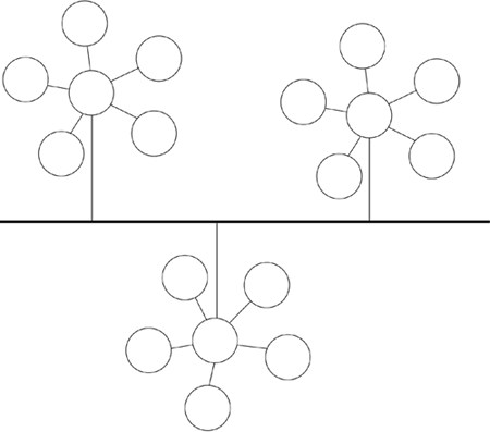
The tree topology is a multitiered hierarchical star topology, in which the endpoint of one spoke in a star is the hub of another, as illustrated in Figure 4-10.
Figure 4-10. Tree Topology

This physical topology is made possible with multiple switches and might be used in an office building where each floor has its own switch, or branch off the tree, connecting to a backbone switch, which provides connectivity between floors, as illustrated in Figure 4-11.
Figure 4-11. Multiswitch LAN

Figure 4-11 shows that the users on the first or second floor LAN can use the server farm resources by the connection provided by the backbone switch. These server farm resources might be web servers, e-mail servers, file servers, network printer servers, or any other server on which multiple users need to share information. For example, compare these two methods for sharing files with someone else in your office: E-mail the file back and forth until all changes are complete; or share and edit the file as it sits on a shared file server. You will likely choose the latter, because editing a shared file is easier to manage than multiple e-mails and revisions. In a medium or large LAN, these servers might be grouped together in one place or distributed across the LAN. For example, each floor could have its own shared file and print server.


