Spanning Tree Protocol Configuration
Before you can understand how a network topology is built and managed using the STP, you need to understand the five states of the spanning tree. If geography isn't your strong suit, that's okay; there are no maps involved when discussing these states.
Spanning-Tree Port States
Because of network delay caused by large LAN segments, topology changes can take place at different times and at different places in the switched network. When a switch port transitions directly from nonparticipation to an active, or forwarding, state, temporary data loops can be created. Ports must wait for new topology information to spread throughout the LAN before frames can be forwarded. Switches must also allow the frame lifetime to expire for frames that have been forwarded using the old topology.
Each port on a switch using STP is in one of the following five states:
Blocking
Listening
Learning
Forwarding
Disabled
Each of these states is discussed in more detail in the following sections. A switch does not enter any of these states immediately, except the blocking state, which is entered on power up. Spanning-tree switch ports move through these five states in the timeframe described as follows:
Initialization to blocking (0 seconds)
Blocking to listening (20 seconds)
Listening to learning (15 seconds)
Learning to forwarding (15 seconds)
Disabled
note
The network administrator can disable a switch port at any time. |
Figure 7-5 illustrates a bridge or switch port moving through the five STP states.
Figure 7-5. Spanning Tree Protocol States
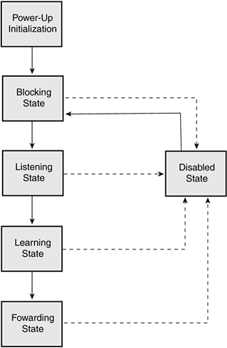
When the STP is enabled, every bridge and switch in the network starts in the blocking state and transitions to the listening and learning states. If properly configured, the ports then stabilize to the forwarding or blocking state until a change in the network is made.
When the spanning-tree algorithm determines that a port is to be in the forwarding state, the following happens:
The port is put into the listening state while waiting for protocol information suggesting it should go to the blocking state.
The port waits for the expiration of a protocol, or forward delay, timer that moves the port to the learning state.
In the learning state, the port continues to block frame forwarding as it learns network host location information for the forwarding database.
The expiration of a protocol (forward delay) timer moves the port to the forwarding state. Both learning and forwarding are enabled while the port is in the forwarding state.
Blocking
A port in the blocking state does not participate in frame forwarding, and after initialization, a BPDU is sent to each port in the switch. A switch assumes it is the root until it exchanges BPDUs with other switches in the network. This BPDU exchange establishes which switch in the network is the root switch. If only one switch resides in the network, no exchange occurs, and after the forward delay timer expires, the ports move to the listening state.
note
A switch always enters the blocking state following switch initialization. |
A port in the blocking state
Discards frames received from the attached network segment.
Discards frames switched from another port for forwarding.
Does not incorporate a host location into its address database; because there is no learning at this point, there is no address database to update.
Receives BPDUs from the network segment and directs them to the switch system module for processing.
Unlike ports in the listening, learning, and forwarding state, a port in the blocking state does not process BPDUs received from the switch system module.
Receives and responds to network management messages, such as a network administrator disabling the port.
After 20 seconds, the switch port moves from the blocking state to the listening state.
Listening
The listening state is the first transitional state for a port after the blocking state. The listening state is where the STP determines that the port should participate in frame forwarding. The switch does not perform any learning or forwarding functions while in the listening state, and it therefore does not incorporate station locations into its address database as it would if the switch were in a blocking state, because there is no address table to update (while in a blocking state). In the listening state, a switch performs the following functions:
Discards frames received from the attached network segment.
Discards frames switched from another port for forwarding.
Receives BPDUs from the network segment and directs them to the switch system module for processing.
Processes BPDUs received from the switch system module.
Receives and responds to network management messages, such as a network administrator disabling the port.
After 15 seconds, the switch port moves from the listening state to the learning state.
Learning
In the learning state, the switch port prepares to participate in the network by forwarding frames. Learning is the second transitional state through which a port moves toward the end goal: frame forwarding. It is the STP that moves the port from the listening to the learning state.
A port in the learning state
Discards frames received from the attached network segment.
Discards frames switched from another port for forwarding.
Incorporates LAN host location information into its address database.
Receives BPDUs from the network segment and directs them to the switch system module for processing.
Receives, processes, and transmits BPDUs received from the system module.
Receives and responds to network management messages, such as a network administrator disabling the port.
After 15 seconds, the switch port moves from the learning state to the forwarding state.
Forwarding
A port in the forwarding state forwards frames across the attached network segment. The forwarding state is the last state a port enters during the creation of the network topology.
A port in the forwarding state
Forwards frames received from the attached network segment.
Forwards frames switched from another port for forwarding.
Incorporates LAN host location information into its address database.
Receives BPDUs from the network segment and directs them to the switch system module for processing.
Processes BPDUs received from the switch system module.
Receives and responds to network management messages, such as a network administrator disabling the port.
A port stays in the forwarding state until a change occurs in the network topology, such as the addition of a new bridge or switch, a new bridge or switch port, or the failure of a bridge, switch, or port. When a change in the topology is detected, all switches recompute the network topology; this process is called convergence.
Disabled
A port in the disabled state does not participate in frame forwarding or the operation of STP because a port in the disabled state is considered nonoperational.
A disabled port
Discards frames received from the attached network segment.
Discards frames switched from another port for forwarding.
Does not incorporate LAN host location information into its address database.
Receives BPDUs, but does not direct them to the switch system module.
Does not receive BPDUs for transmission from the switch system module.
Receives and responds to network management messages, such as notification of a network administrator enabling a port.
Spanning-Tree Operation
Just as a spanning-tree switch has a value, so do the individual ports on the switch, called the port cost. As discussed earlier, the port cost is determined based on the network bandwidth, or speeds that the port supports; the faster the port, the lower its cost.
Table 7-1 lists the default IEEE costs associated with common port speeds.
Link Speed | Port Cost |
|---|---|
Gigabit Ethernet | 4 |
Fast Ethernet (100 megabits per second [Mbps]) | 10 |
Ethernet (10 Mbps) | 100 |
A switch uses the port cost to determine the root port for each switch in the network. All nonroot bridges have one root port that is used as the link over which data traffic is forwarded across the network.
note
The root port represents a switch's lowest-cost path to the root bridge, and, by default, all ports on the root bridge are also root ports and have a cost of 0. Because root ports are directly connected to the root bridge, their cost to reach the root bridge is 0. |
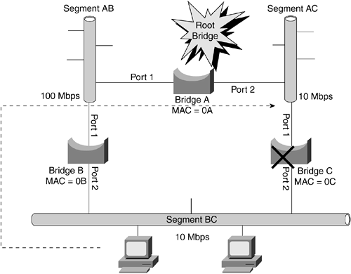
Figure 7-6 shows a network with three bridges. Bridge A has been made root bridge 7 because it has the lowest MAC address; because all bridge priorities are equal, the bridge with the lowest MAC address is elected the root.
Figure 7-6. Network with Three Bridges
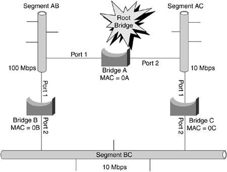
The following three items characterize the network topology shown in Figure 7-6:
Bridge B is connected to Bridge A via a 100-Mbps link, and Bridge C is connected to Bridge A via a 10-Mbps link.
Bridges B and C are connected to one another at 10 Mbps via Segment BC.
Segment BC creates a loop in this network.
Because this network has a loop, the STP determines which links remain in a forwarding mode and which enter a blocking mode.
Bridge A is elected as the root bridge because it has the lowest MAC address based on the STP information exchanged by the BPDUs between bridges in this network. In this case, the root bridge sends out BPDUs with a port cost of 0; and because it is the root bridge, there is no cost for its own ports to reach it. Therefore, the port cost is 0. These BPDUs will be received on port 1 on Bridge B and Bridge C.
When these BPDUs are received by Bridge B, it (Bridge B) adds its own port cost to the cost provided by the root bridge; because the cost associated with a 100-Mbps port is 19, Bridge B port 1 determines that it can reach the root bridge with a total cost of 19. Port 1 of Bridge C, connected at 10 Mbps, determines that it can reach the root bridge with a total cost of 100 (100 + 0).
note
By default, BPDUs are sent across the network every two seconds. |
Remember Bridge B and Bridge C are connected to Network 1 and also send out BPDUs on their interface connected to this network?port 2 for both bridges. Bridge B sends a BPDU to Bridge C over this network segment (Segment BC). In this BPDU, Bridge B announces to Bridge C that it can reach the root bridge with a cost of 19. When this message reaches Bridge C, it adds its port 2 cost to this value, calculating that it can reach the root bridge with a total cost of 119 (100 + 19) via port 2.
Bridge C now knows that it can reach the root bridge through port 1 with a cost of 100, or through port 2 with a cost of 119. Based on these two paths, Bridge C determines that port 1 should be its root port because of its lower cost to the root.
Bridge C also sends BPDUs to Bridge B across Segment BC. In these BPDU messages, Bridge C announces a cost to the root bridge of 100. When these BPDUs are received by Bridge B, Bridge B adds this cost to the cost of its port 2 interface. Bridge B now also knows that it can reach the root bridge, via Bridge C, with a total cost of 200. Based on the two possible paths, Bridge B determines that port 1 should be its root port because of its lower-cost path to the root.
Remember, the shortest distance between two points is a straight line, or in the case of STP, the lower cost.
Designated Ports
In the small network described previously, you have determined which port(s) should be the root ports on network bridges; however, which ports will be in a blocking or forwarding mode must still be determined.
For example, Segment BC has two possible paths to the root bridge: one via port 2 on Bridge B and the other via port 2 on Bridge C. To eliminate this loop, one of these two ports must be placed in a blocking mode, as illustrated in Figure 7-7.
Figure 7-7. Bridge C with a Blocked Port
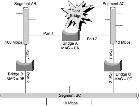
On a spanning-tree network, each network segment has one port identified as the designated port. The designated port is the port that is the single interface to forward traffic to the root bridge, and is determined via another election using BPDUs.
The network illustrated in Figure 7-7 contains three segments: Segment AC, Segment AB, and Segment BC. On each segment, one of the connected bridge ports needs to be elected as the designated port. This is always the switch port on the segment with the lower port cost. For example, on Segment BC, two paths via port 2 on Bridge B and Bridge C are available to the root bridge, forming a loop. In this case, port 2 on Bridge B and Bridge C has a port cost of 100 on Segment BC, as illustrated in Figure 7-8.
Figure 7-8. Traffic Path from Segment BC to Segment AC
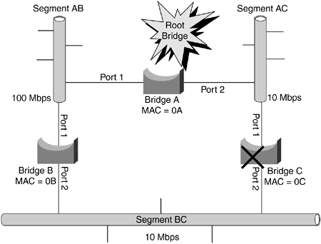
Because both bridges, Bridge B and Bridge C, have equal port costs to each other, MAC addresses are used to determine the designated port, making Bridge B the designated port on Segment BC because it has the lower MAC address. Therefore, port 2 on Bridge B will be placed in forwarding mode, and port 2 on Bridge C in blocking mode. When these forwarding and blocking modes are established, all traffic from Segment BC will exit the segment via Bridge B.
Convergence
After the transfer of BPDUs between systems has determined the root bridge and the root port of each bridge and switch, the network is loop free. The next topic is how the STP functions when something goes wrong in the network, such as a link failure. After the STP topology of a network has been calculated, each bridge and switch forwards BPDUs every two seconds. These BPDU messages inform the bridges and switches of which links are still active in the network, and which bridges and switches are not. For example, Bridge B in the network example illustrated in the Figure 7-9 could have failed or been powered down.
Figure 7-9. Bridge B Failure
In this case, Bridge C fails to receive BPDU messages from Bridge B on Bridge C's port 2 interface. Even though Bridge C port 2 is in blocking mode, it continues receiving and analyzing BPDU messages. After 20 seconds have passed without Bridge C receiving a BPDU on port 2 from Bridge B, Bridge C assumes that Bridge B is not available and transitions into the listening state. The listening state lasts for 15 seconds and is the time when Bridge B will be listening to and inspecting BPDUs from all other bridges. The bridge port still does not forward traffic during the listening stage.
After the 15 seconds of the listening state expire, the Bridge C port transitions into a learning state for another 15 seconds. During this time, Bridge C port 2 learns the MAC addresses of all connected hosts on the network segment. As it is with the listening state, Bridge C port 2 does not forward traffic during this learning state.
When the learning state is completed, Bridge C port 2 transitions into forwarding mode, in which it forwards traffic as the active path to the root bridge; at this point, the network is considered to be converged.
note
During the 50 seconds the network is converging on the change, no traffic is forwarded to or from any of the network bridges and switches. In today's network environment, 50 seconds can seem like an eternity. The Rapid Spanning Tree Protocol (RSTP, IEEE 802.1w) is available to address this issue (the length of time required to transition from the blocking to forwarding state); RSTP enables designated ports to change from the blocking to forwarding state in a few seconds. The exact amount of time depends on the interval between hello timers in your network. Because RSTP does not use timed intervals, as STP does, it is difficult to discuss the precise amount of time it will take an RSTP network to converge. It is because of this lack of precise timing that convergence in an RSTP network can best be measured in "a few seconds." |


