1.1 What Is the UML?
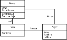
Quite simply, the UML is a visual language for modeling and communicating about systems through the use of diagrams and supporting text. For example, Figure 1-1 communicates the following:
A manager leads a team that executes a project.
Each manager has a name and phone number, and may initiate a project or terminate a project.
Each project has a name, start date, and end date.
Each team has a description, and that is all we are interested in concerning the team.
Don't worry if Figure 1-1 does not make complete sense. We will explore this figure and the UML in more detail in Chapter 2.
Figure 1-1. Managers, projects, and teams

1.1.1 The Three Aspects of UML
As you know by now, UML is an abbreviation for Unified Modeling Language. Each of these words speaks to an important aspect of the UML. The next few sections talk about these aspects, working through the words of the abbreviation in reverse order.
1.1.1.1 Language
A language enables us to communicate about a subject. In system development, the subject includes the requirements and the system. Without a language, it is difficult for team members to communicate and collaborate to successfully develop a system.
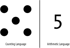
Languages, in the broad sense, are not always composed of written words. For example, we commonly use "counting language" to introduce children to counting and arithmetic. A child is given a number of apples, oranges, pebbles, or some other type of object to represent a quantity. For the child, the representation of five might end up being five apples. The operations of addition and subtraction are then represented by the physical action of adding or removing objects from the child's collection. We adults, on the other hand, prefer the language of arithmetic, which represents a specific quantity using a string of Arabic numerals, and which uses the + and - operators to represent addition and subtraction.
Figure 1-2 contrasts a young child's counting language with the more abstract arithmetic language used by adults.
Figure 1-2. The quantity five in two "languages"

Now consider these two languages for communicating some specific number of days for a project. To model and express the quantity of five, the counting language uses five objects while arithmetic uses the string "5". To model and express a more involved quantity of, say, 365, the counting language uses 365 objects (however, having so many objects may be impractical), while the arithmetic language uses the string "365". To model and express the quantity of four and a half, the counting language uses 4 objects and one half of an object (again, however, one half of an object may or may not be practical), and arithmetic uses the string "4.5". Because arithmetic allows us to more easily and practically represent a wider range of quantities than the counting language, arithmetic is said to be more expressive than the counting language. Likewise, a quantity is expressed more concisely using arithmetic rather than the counting language. By using languages that are more expressive, we can communicate complex information about complex subjects in a more concise manner than would be possible otherwise.
Stated somewhat formally, the UML is a language for specifying, visualizing, constructing, and documenting the artifacts of a system-intensive process. A system-intensive process is an approach that focuses on a system, including the steps for producing or maintaining the system given the requirements the system must meet. Specifying involves the creation of a model that describes a system. Visualizing involves the use of diagrams to render and communicate the model (the model is the idea and the diagrams are the expression of the idea). Constructing involves the use of this visual depiction to construct the system, similar to how a blueprint is used to construct a building. Documenting uses models and diagrams to capture our knowledge of the requirements and of the system throughout the process.
The UML itself is not a process. A process applies a set of steps described by a methodology to solve a problem and develop a system that satisfies its user's requirements. A method addresses only part of the development process; for example, requirements gathering, analysis, design, and so forth, whereas a methodology addresses the whole development process from requirements gathering until the system is made available to its users. The different ways for gathering and using requirements, analyzing requirements, designing a system, and so forth are known as techniques. Artifacts are work products that are produced and used within a process, including documentation for communication between parties working on a system and the physical system itself. Each type of UML diagram is also known as a modeling technique.
1.1.1.2 Model
A model is a representation of a subject. For example, as I noted earlier, to model and express the quantity of five, the counting language uses five objects, whereas arithmetic uses the string "5". A model captures a set of ideas known as abstractions about its subject. Without a model, it is very difficult for team members to have a common understanding of the requirements and the system, and for them to consider the impact of changes that occur while the system is being developed.
When creating a model, if we try to represent everything about the subject all at once, we will be easily overwhelmed by the amount of information. Therefore, it is important to focus on capturing relevant information required for understanding the problem at hand, solving that problem, and implementing the solution, while excluding any irrelevant information that may hinder our progress. By managing what abstractions make up a model, how detailed they are, and when to capture them throughout the development process, we can better manage the overall complexity involved in system development.
1.1.1.3 Unified
The term unified refers to the fact that the Object Management Group (OMG), an industry-recognized standardization organization, and Rational Software Corporation created the UML to bring together the information systems and technology industry's best engineering practices. These practices involve applying techniques that allow us to more successfully develop systems. Without a common language, it is difficult for new team members to quickly become productive and contribute to developing a system.
1.1.2 Goals and Scope
By understanding the OMG's goals and scope for the UML, we can better understand the motivations behind the UML. The OMG's goals were to make the UML:
Ready to use
Expressive
Simple
Precise
Extensible
Implementation-independent
Process-independent
By being ready to use, expressive, simple, and precise, the UML can immediately be applied to development projects. To enable the development of precise models, the OMG introduced the Object Constraint Language (OCL), a sublanguage for attaching conditions that the elements of a model must satisfy for the model to be considered correct (also known as well formed). The OCL is discussed in Chapter 10.
An extensible language allows us to define new concepts, similar to introducing new words and extending the vocabulary of a natural language. Extensibility is discussed in Chapter 9. An implementation-independent language may be used independently of any specific implementation technologies, such as Java or .NET. A process-independent language may be used with various types of processes.
The OMG's scope when creating the UML included combining the modeling languages of three of the most prominent system-development methods Grady Booch's Booch `93 method, James Rumbaugh's Object Modeling Technique (OMT) -2 method, and Ivar Jacobson's Object-Oriented Software Engineering (OOSE) method with the information systems and technology industry's best engineering practices. Separately, these are only methods, but together, they form a fairly complete methodology.
1.1.3 History
The UML's history consists of five distinct time periods. By understanding these periods, you can understand why the UML emerged and how it is still evolving today.
1.1.3.1 The fragmentation period
Between the mid-1970s and the mid-1990s, organizations began to understand the value of software to business but only had a fragmented collection of techniques for producing and maintaining software. Amongst the various emerging techniques and methods that focused on producing and maintaining software more effectively (each having its own modeling languages), three methods stood out:
Grady Booch's Booch `93 method (from Booch `91) emphasized the design and construction of software systems.
James Rumbaugh's Object Modeling Technique (OMT) -2 method (from OMT-1) emphasized the analysis of software systems.
Ivar Jacobson's Object-Oriented Software Engineering (OOSE) method emphasized business engineering and requirements analysis.
As object-oriented methods began to evolve from structured methods, the industry fragmented around these threeand othermethods. Practitioners of one method could not easily understand artifacts produced using a different method. In addition, practitioners encountered problems moving from one organization to the next because such a move frequently entailed learning a new method. Furthermore, tool support was nonexistent to minimal because there were so many methods. Therefore, it was often cost prohibitive to use any method at all.
1.1.3.2 The unification period
Between the mid-1990s and 1997, the UML 1.0 emerged. James Rumbaugh, and later Ivar Jacobson, joined Grady Booch at Rational Software Corporation to unify their approaches. Because of their unification effort, they became known as the Three Amigos. As organizations began to see the value of the UML, the OMG's Object Analysis and Design Task Force issued a Request for Proposal (RFP) to establish a standard that defines the meaning of object-oriented technology concepts for tools that support object-oriented analysis and design. Together with various other organizations, Rational Software Corporation formed the UML Partners Consortium, and the partners submitted Version 1.0 of the UML to the OMG as one of many initial RFP responses.
1.1.3.3 The standardization period
In the later half of 1997, the UML 1.1 emerged. All the RFP responses were combined into Version 1.1 of the UML. The OMG adopted the UML and assumed responsibility for further development of the standard in November 1997.
1.1.3.4 The revision period
After adoption of the UML 1.1, various versions of the UML emerged. The OMG charted a revision task force (RTF) to accept public comments on the UML and make minor editorial and technical updates to the standard. Various product and service vendors began to support and promote the UML with tools, consulting, books, and so forth. The current version of the UML is 1.4, and the OMG is currently working on a major revision, UML 2.0.
1.1.3.5 The industrialization period
In parallel with the revision period, the OMG is proposing the UML standard for international standardization as a Publicly Available Specification (PAS) via the International Organization for Standardization (ISO). The most current version of the UML specification is available from the OMG at http://www.omg.org.


