7.2 Transitions
Given the states of an element, how are they related to one another? Transitions address this question. As discussed in Chapter 2, transitions between states occur as follows:
An element is in a source state.
An event occurs.
An action is performed.
The element enters a target state.
When an event occurs, the transition is said to fire. In the UML, a transition is shown as a solid line from a source state to a target state labeled with the event followed by a forward slash followed by the action, where the event and action are optional and the forward slash is used only if an action is shown. The next few sections discuss events and actions.
|
7.2.1 Events
An event is an occurrence, including the reception of a request. For example, the project management system may respond to the following events:
- Startup
-
Indicates that the project management system will become active if it is inactive.
- Shutdown
-
Indicates that the project management system will become inactive if it is active.
- Severe Error
-
Indicates that the project management system has encountered a severe error, perhaps because it is running low on secondary storage, and will become suspended if it is active.
- Reset
-
Indicates that the project management system will become active if it is suspended.
In the UML, an event is described using the following UML syntax:
event_name (parameter_list) [guard]
in which:
- event_name
-
Is the name of the event. An event usually has the same name as an operation of the element to which the state diagram pertains; therefore when the element receives the event, that operation is invoked.
- parameter_list
-
Is optional, and is a comma-separated list that indicates the parameters passed to the event. Each parameter may be an explicit value or a variable. The parentheses are not used when the event does not require any parameters.
- guard
-
Is optional, and indicates a condition that must be satisfied for the transition to fire, or occur. The square brackets are not shown when a guard is not specified.
The UML also allows you to show an event using pseudocode or another language. For example, you can use the syntax of Java, C++, C#, or some other programming language.
Following is an example of an event defined using the syntax just shown. The event informs the project management system to start up:
Startup
If this event requires the user's identification, you can update the event to the following:
Startup (UserID)
If the project management system responds to this event only if it can start up, perhaps if enough memory is available, you can update the transition to the following:
Startup (UserID) [Enough memory is available]
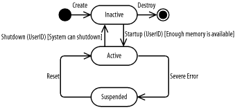
Figure 7-3 shows this transition occurring between the Inactive state, which indicates that the project management system is not available for processing, and the Active state, which indicates that the project management system is available for processing.
Figure 7-3. Transitions with events

Figure 7-3 also shows a transition originating from the initial state labeled with the event that creates an instance of the project management system and a transition to the final state labeled with the event that destroys an instance of the project management system. Finally, Figure 7-3 shows the various events associated with the project management system, including the Startup, Shutdown, Sever Error, and Reset events.
7.2.2 Actions
An action represents processing. For example, the project management system may respond to events with the following actions:
- LogMessage
-
Indicates that the project management system will log a message in its history file. This file is used for logging the project management system's processing and may be used for diagnosing problems, and so forth.
- getDateAndTime
-
Indicates that the operating system returns the current date and time from the operating system.
In the UML, an action is described using the following UML syntax:
return_variable := target_element.action_name (argument_list)
in which:
- return_variable
-
Is optional, and indicates a name for the value returned by the action to be invoked in response to the event. If you choose not to show a return variable or the action does not return a value, you should omit the succeeding colon and equal sign.
- target_element
-
Is the name of the element that will perform the action. If the same element that receives the event will perform the action, the target element is not shown and you should omit the succeeding period.
- action_name
-
Is the name of the action. An action usually has the same name as an operation of the element to which the state diagram pertains, or as an operation of the target element, if one is specified; therefore, when the action is invoked, the element receives the event, and the operation is invoked.
- argument_list
-
Is optional, and is a comma-separated list that indicates the arguments passed to the action. Each parameter may be an explicit value or a variable. The parentheses are removed when the action does not require any arguments.
The UML also allows you to show an action using pseudocode or another language. For example, you can use the syntax of Java, C++, C#, or some other programming language.
Continuing with the example from the previous section, the following action passes the user's time zone to the operating system (OS) using the getDateAndTime operation:
OS.getDateAndTime (TimeZone)
If this action returns some output data (the current date and time), you can update the action to the following:
DT := OS.getDateAndTime (TimeZone)
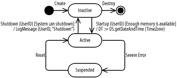
Figure 7-4 updates Figure 7-3 and shows the events and actions for the transitions between the Inactive and Active states. You can see the logging of a message using the LogMessage action when the system is shut down, and you can see that the Startup event triggers the retrieval of the date and time using the getDateAndTime action of the OS object, which represents the operating system.
Figure 7-4. Transition with events and actions


