Radio Interface
3.3 Radio Interface
3.3.1 Physical Layer Principles
3.3.1.1 Packet Data Channel
The GPRS physical layer is based on that of the GSM (see Chapter 1). The access scheme is TDMA, with eight basic physical channels per carrier (TS 0 to 7).
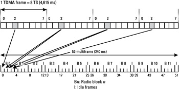
A physical channel uses a combination of frequency- and time-division multiplexing and is defined as a radio frequency channel and time slot pair. The physical channel that is used for packet logical channels is called a packet data channel (PDCH). PDCHs are dynamically allocated in the cell by the network. The PDCH is mapped on a 52-multiframe, as shown in Figure 3.10. The 52-multiframe consists of 12 radio blocks (BO to B11) of 4 consecutive TDMA frames and 4 idle frames (frames 12, 25, 38, and 51), amounting to a total of 52 frames.
 Figure 3.10: Time slots and TDMA frames.
3.3.1.2 Packet Data Logical Channel
GPRS, like GSM, uses the concept of logical channels mapped on top of the physical channels. Two types of logical channels have been introduced, namely traffic channels and control channels. Three subtypes of control channels have been defined for GPRS: broadcast, common control, and associated. In addition, the GSM common control channels (BCCH, CCCH, and RACH) may be used to access the network and establish packet transfer.
The different packet data logical channels are:
-
Packet broadcast control channel (PBCCH). The presence of PBCCH in the cell is optional. The PBCCH broadcasts information relative to the cell in which the mobile camps and information on the neighbor cells. This information is used by the mobile in order to access the network. When there is no PBCCH in the cell, the information needed by the mobile to access the network for a packet transfer is broadcast on BCCH.
-
Packet common control channel (PCCCH). The PCCCH is present in the cell only if the PBCCH is present in the cell. When it is not present in the cell, the common control signaling for GPRS is handled on the GSM common control channels (CCCH). PCCCH is composed of packet random access channel (PRACH), used for random access, packet paging channel (PPCH), used for paging, and packet access grant channel (PAGCH), used for access grant. The PRACH is used by the MS to initiate uplink access to the network. The PPCH is used by the network to page the mobile in order to establish a downlink packet transfer. The PAGCH is used by the network to assign radio resources to the mobile for a packet transfer.
-
Packet data traffic channel (PDTCH). The PDTCH is used to transfer user data during uplink or downlink packet transfer. The PDTCH is a unidirectional channel, either uplink (PDTCH/U) for a mobile-originated packet transfer or downlink (PDTCH/D) for a mobile-terminated packet transfer. A PDTCH is a resource allocated on one physical channel by the network for user data transmission.
-
Packet associated control channel (PACCH). The PACCH is a unidirectional channel that is used to carry signaling during uplink or downlink packet data transfer. The uplink PACCH carries signaling from the MS to the network and the downlink PACCH carries signaling from the network to the mobile. The PACCH is dynamically allocated on a block basis.
-
Packet timing advance control channel (PTCCH). The PTCCH is a bidirectional channel that is used for TA update. The PTCCH is an optional channel. The PTCCH when present is mapped on frames number 12 and 38 of the 52—multiframe.
Table 3.2 lists the various GPRS logical channels.
|
Logical Channel |
Abbreviation |
Uplink/ Downlink |
Task |
|---|---|---|---|
|
Packet broadcast control channel |
PBCCH |
DL |
Packet system broadcast information |
|
Packet paging channel |
PPCH |
DL |
MS paging for downlink transfer establishment |
|
Packet random access channel |
PRACH |
UL |
MS random access for uplink transferestablishment |
|
Packet access grant channel |
PAGCH |
DL |
Radio resources assignment |
|
Packet timing advance control channel |
PTCCH |
UL/DL |
Timing advance update |
|
Packet associated control channel |
PACCH |
UL/DL |
Signaling associated with data transfer |
|
Packet data traffic channel |
PDTCH |
UL/DL |
Data channel |
3.3.1.3 Multislot Classes Definition
In order to provide higher throughputs, a GPRS MS may transmit or receive in several time slots of the TDMA frame. The multislot capability is indicated by the multislot class of the GPRS MS. This multislot class is defined by several parameters such as the maximum number of time slots supported by the MS per TDMA frame in uplink and in downlink. The multislot class of the MS is sent to the network during the GPRS attach procedure. A detail of multislot classes is given in Section 4.2.1.
3.3.1.4 Cell Reselection
In GPRS as in GSM, the mobile performs cell reselection. However, there are some differences compared with GSM.
In GPRS the mobile performs cell reselection when it is in idle mode but also during packet transfer. The cell reselection is either performed by the mobile autonomously or optionally controlled by the network. Unlike GSM, there is no handover in GPRS but only cell reselections. So when there is a reselection during a packet transfer, this latter is interrupted and it has to be started again in the new cell. There is an interruption of the packet transfer during the reselection phase.
Although the GPRS cell reselection algorithms used by the mobile are based on the same principles as those used in GSM, they have been slightly modified in order to provide more flexibility. These algorithms are described in Section 5.3.
3.3.1.5 Radio Environment Monitoring
The MS performs different types of radio measurements that are reported to the network and used by it for RLC. These estimations are also used by the mobile itself to compute its transmission power (open-loop power control; see Section 4.1.3.1), for cell selection and cell reselection.
The mobile performs the following types of measurement:
-
Received signal level (RXLEV) measurements. The RXLEV measurements are performed on both serving cell and neighbor cells for the purpose of cell reselection. During packet-transfer mode (see Section 3.3.2.1), the serving cell RXLEV measurement can also be used for downlink coding scheme adaptation (see Section 4.1.2.1), network-controlled cell reselection, and downlink and uplink power control.
-
Quality (RXQUAL) measurements. The RXQUAL is computed from the average BER before channel decoding. During packet-transfer mode the mobile estimates the quality of the downlink blocks it receives. In packet idle mode, no quality measurements are performed. The RXQUAL can be used by the network for network-controlled cell reselection, dynamic coding scheme adaptation, and downlink power control. The RXQUAL is the current GSM quality indicator.
-
Interference measurements. These measurements have been introduced for GPRS. They correspond to a received signal level measurement performed on a frequency that is different from a beacon frequency. The interest is in having an estimation of the interference level on the PDTCH. It can be used by the network to optimize the mobile RR allocation, to select a more appropriate coding scheme, to trigger a network-controlled cell reselection, and for power control or for network statistics.
The measurements are either used by the MS for its own purposes or by the network. The RXLEV and RXQUAL measurements are also performed at the BSS side for each MS. They are used for network-controlled cell reselection, uplink power control (closed loop, see Section 4.1.3.1), and dynamic coding scheme adaptation.
3.3.1.6 Principles of Power Control
Power control can be used in order to improve the spectrum efficiency while maintaining radio link quality and reducing the power consumption in the MS. Power control in GPRS is more complicated than for a circuit-switched connection, since there is not necessarily a continuous two-way connection.
Note that power control can be performed in both uplink and downlink directions. Uplink power control and downlink power control are described in Sections 4.1.3.1 and 4.1.3.2, respectively.
3.3.1.7 Channel Coding
The GPRS user data is sent on radio blocks encoded with one of four channel coding schemes (CS1, CS2, CS3, CS4). The GPRS signaling is sent with the CS1 channel coding scheme. This scheme provides the highest protection level against error transmission, while the CS4 channel coding scheme provides the lowest protection level. The more the channel coding scheme provides an efficient protection level against error transmission, the more the useful data throughput decreases due to redundant information added to source data. The channel coding scheme used on uplink and downlink depends on the radio quality between the network and the MS. Table 3.3 gives the throughputs associated with each coding scheme.
|
Coding Scheme |
Throughput (Kbps) |
|---|---|
|
CS-1 |
9.05 |
|
CS-2 |
13.4 |
|
CS-3 |
15.6 |
|
CS-4 |
21.4 |
3.3.2 RR Management Principles
3.3.2.1 RR Operating Modes
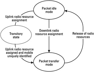
At the RR level, the MS behavior is dependent on two operating RR states. These states, packet idle mode and packet transfer mode, allow the RR activity of the MS to be characterized.
Packet Idle Mode
When the MS is in packet idle mode, no radio resources are allocated. Leaving packet idle mode occurs when upper layers request the transfer of uplink data requiring the assignment of uplink resources from the network. It also occurs at the reception of a downlink resource assignment command from the network for a downlink transfer.
In case of downlink transfer, the mobile switches from packet idle mode to packet transfer mode when it receives the downlink assignment command from the network. In the case of uplink transfer, the mobile leaves packet idle mode when it requests the assignment of uplink resources to the network. However, switching to packet transfer mode is not instantaneous. The mobile switches to packet transfer mode only when it has been uniquely identified at the network side; this will be explained in more detail in Chapter 5. Thus there is a period between packet idle mode and packet transfer mode during which the mobile is in a transitory state.
During packet idle mode, the MS listens to its PCH and the CBCH. This last one is the PBCCH when present in the cell; otherwise it is the BCCH.
Packet Transfer Mode
When the MS is in packet transfer mode, it is clearly identified at the network side and uplink or/and downlink radio resources are allocated.
Switching from packet transfer mode to packet idle mode occurs when the network releases all downlink and uplink resources. This transition can also occur in the case of an abnormal condition during packet transfer mode (e.g., radio link failure) or when the mobile decides on a cell reselection toward a new cell.
During packet transfer mode, the mobile transmits and receives data. Figure 3.11 summarizes the transition between the different RR states.

Figure 3.11: Transition between RR operating modes.
3.3.2.2 Temporary Block Flow
A temporary block flow (TBF) is a physical connection between the RR entity in the MS and the RR entity at the network side to support the unidirectional transfer of LLC protocol data units over PDCH. A TBF is characterized by one or several PDCHs allocated by the network to an MS for the duration of the data transfer. Once the data transfer is finished, the TBF is released.
When the mobile must send continuous data to the network, it requests the establishment of an uplink TBF by sending signaling information over CCCH or PCCCH. When the network wants to send data to the mobile, it assigns a downlink TBF between the two RR entities.
A downlink TBF supports the transfer of data from the network to the mobile, while an uplink TBF supports the transfer of data from the mobile to the network. One uplink and one downlink TBF can be supported at the same time between the two RR entities. These two TBFs are defined as concurrent TBFs.
The number of TBFs per mobile and per direction is limited to one. However TBFs belonging to different mobiles can share the same PDCH.
| Note |
As a packet transfer session is composed of a lot of requests, responses, and acknowledgments, many consecutive uplink and downlink TBFs are established for the same session (e.g., Web browsing). |
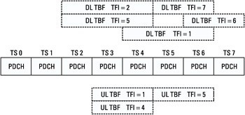
Each TBF is identified by a temporary flow identifier (TFI) assigned by the network. So in case of concurrent TBFs, one TFI identifies the uplink TBF and another one the downlink TBF. The TFI is used to differentiate TBFs sharing the same PDCHs in one direction.
Figure 3.12 gives an example of TBF mapping for different mobiles onto PDCHs. A downlink TBF, identified by a TFI equal to 2, has assigned resources on the PDCH numbers 2, 3, and 4, while another downlink TBF identified by a TFI equal to 1 has assigned resources on the PDCH numbers 4, 5, and 6. An uplink TBF identified by a TFI equal to 4 has assigned resources on the PDCH numbers 3 and 4.

Figure 3.12: Example of mapping of TBFs with their respective TFI onto PDCHs.
3.3.2.3 Allocation Modes on the Uplink
Several MSs may be multiplexed on the same PDCH. In order to share the uplink bandwidth between several mobiles mapped on the same PDCH, different allocation schemes have been defined to allocate an uplink radio block instance to a particular mobile.
Three allocation schemes exist for medium access control:
-
Dynamic allocation;
-
Extended dynamic allocation;
-
Fixed allocation.
The second scheme is optional for the mobile while the others are mandatory. On the network side, either fixed allocation or dynamic allocation must be implemented. Extended dynamic allocation is optional for the network.
Dynamic Allocation
In principle, dynamic allocation allows uplink transmission to mobiles sharing the same PDCH, on a block-by-block basis. During the uplink TBF establishment, an uplink state flag (USF) is given to the MS for each allocated uplink PDCH. The USF is used as a token given by the network to allow transmission of one uplink block.
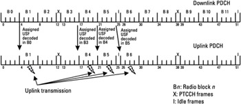
Whenever the network wants to allocate one radio block occurrence on one uplink PDCH, it includes, on the associated downlink PDCH, the USF in the radio block immediately preceding the allocated block occurrence. When the mobile decodes its assigned USF value in a radio block sent on a downlink PDCH associated with an allocated uplink one, it transmits an uplink radio block in the next uplink radio block occurrence, that is, the B(x) radio block if the USF was detected in the B(x- 1) radio block.
The principle of dynamic allocation is illustrated in Figure 3.13.

Figure 3.13: Principle of dynamic allocation.
The USF is included in the header of each downlink RLC/MAC block. The USF coding (3 bits) enables eight mobiles to be multiplexed on the same uplink PDCH.
Dynamic allocation implies the constant monitoring (radio block decoding) of the downlink PDCHs associated with the allocated uplink PDCHs.
As explained previously, the USF allows the sending of one block in the next uplink occurrence. However, dynamic allocation can also be used in such a way that the decoding of one USF value allows the mobile to send four consecutive uplink blocks on the same PDCH. The choice between one block or four blocks is indicated during the TBF establishment by the network to the mobile.
The concept of USF granularity has been introduced in order to indicate the number of uplink radio blocks to be sent upon detection of the assigned USF by the MS. The USF granularity is conveyed to the MS during the uplink TBF establishment. Thus it involves the MS transmitting either a single radio block or a sequence of four consecutive radio blocks starting on the B(x) radio block if the USF was detected in the B(x - 1) radio block.
Extended Dynamic Allocation
The extended dynamic allocation scheme offers an improvement over the dynamic allocation scheme. Some RR configurations are not compliant with all MS multislot classes in the dynamic allocation scheme. In the dynamic allocation scheme, the MS must decode all USF values on all downlink PDCHs associated with the allocated uplink PDCHs.
The mobile monitors its assigned PDCHs starting from the lowest numbered one (the one that is mapped on the first allocated time slot in the TDMA frame), then it monitors the next lowest numbered time slot, and so on. Whenever the MS detects its assigned USF value on a PDCH, it transmits one radio block or a sequence of four radio blocks on the same PDCH and all higher-numbered assigned PDCHs. The mobile does not need to monitor the USF on these higher PDCHs. This is of particular interest in some RR configurations that are not compliant with all MS multislot classes in the dynamic allocation scheme.
Let us take the example of a class 12 MS, which is defined by:
-
A maximum number of four receive time slots per TDMA frame;
-
A maximum number of four transmit time slots per TDMA frame;
-
A total number of transmit and receive time slots per TDMA frame less than or equal to five.
The network cannot allocate four uplink PDCHs to a MS multislot class 12 with the dynamic allocation. Indeed, the MS must decode the USF fields on the four associated downlink PDCHs. This means that the MS would have to receive on four time slots to be able to transmit on four time slots. That gives a total number of eight received and transmit time slots, which is not compliant with a multislot class 12 MS. In the case of extended dynamic allocation, the network can allocate four uplink PDCHs without exceeding a total number of five receive and transmit time slots.
Fixed Allocation
Fixed allocation enables a given MS to be signaled predetermined uplink block occurrences on which it is allowed to transmit. The network assigns to each mobile a fixed uplink resource allocation of radio blocks onto one or several PDCHs.
The network allocates uplink radio blocks using bitmaps (series of zeros and ones). A 0 indicates that the mobile is not allowed to transmit, and a 1 indicates a transmission occurrence. The bitmaps are sent during the establishment of the uplink TBF. If more uplink resources are required during the uplink TBF, the network sends a bitmap in downlink on the PACCH.
A fixed allocation TBF operates as an open-ended TBF when an arbitrary number of octets are transferred during the uplink TBF. When the allocated bitmap ends, the MS requests a new bitmap if it wishes to continue the TBF.
A fixed allocation TBF operates as a close-ended TBF when the MS specifies the number of octets to be transferred during the uplink TBF establishment.
Comparison of Allocation Schemes
Fixed allocation allows for an efficient usage of the MS multislot capability, as the downlink monitoring is limited to one time slot (listening of the PACCH). The advantage of dynamic allocation is that the management of uplink resources is much more flexible.
From an implementation point of view, dynamic allocation is easier to implement on the network side. An efficient management of bitmap in fixed allocation is not so easy compared with USF handling. In fact, the management of resource allocation with anticipation (as needed in fixed allocation) is made more complex by the bursty nature of packet transfer. Most of the time the duration of the uplink TBF is completely unknown at the network side at the beginning of the TBF. This is why it is very difficult to manage radio block allocation at the beginning of the TBF. If the bitmap allocation is too short, the reaction time of the network for reallocation of new bitmaps will increase the duration of the TBF. If the bitmap allocation is too large compared with the TBF duration, block bitmap will be reallocated at the network side in order to avoid waste of uplink resources. Dynamic allocation is very easy to manage, since the USF allocation needs to anticipate only a few block periods.


