PLL
4.1 PLL
This section describes the mechanisms that are used to guarantee an acceptable radio link quality between the MS and the BTS. After the discussion of physical channels, we will look at issues such as channel coding, uplink and downlink power control, and radio environment quality measurements.
4.1.1 Mapping of Logical Channels on the 52-Multiframe
The concept of logical and physical channels described for GSM also exists in GPRS. The difference with GSM is the possibility of dynamically configuring the mapping of the logical channels onto the physical channels. This feature allows the system to adapt itself to the network load, by allocating or releasing resources whenever needed.
The GPRS multiframe length is 52 TDMA frames, and it is organized into 12 blocks (BO to B11) of 4 consecutive TDMA frames, plus 4 idle frames. A physical channel is referred to as a PDCH. A PDCH may be fully defined by ARFCN and a time slot pairing. Radio blocks, consisting of four bursts on a given PDCH, are used to convey the logical channels, transmitting either data or signaling (see Section 3.3.1.2 for the definition of the GPRS logical channels). The first and third idle frames within the 52-multi-frame are used for the PTCCH on both uplink and downlink. This is represented in Figure 4.1.
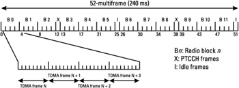 Figure 4.1: The 52-multiframe.
A PDCH that supports PCCCHs is called a master channel because it carries all control signaling on PCCCH for packet transfer establishment. A master channel also carries user data (PDTCH) and dedicated signaling (PACCH). The other PDCHs that do not support PCCCHs are called slave PDCHs. They carry only user data and dedicated signaling. The logical channels are dynamically mapped onto the multiframe. This is possible by means of different parameters that are transmitted to the MS in order to specify the number of blocks that are reserved for the different channels.
4.1.1.1 Uplink Channel Organization
A master channel configuration on the uplink may contain the following packet data logical channels: PRACH + PDTCH + PACCH + PTCCH. To map these channels on the multiframe, the MS uses an ordered list of blocks: B0, B6, B3, B9, B1, B7, B4, B10, B2, B8, B5, B11. A first group of blocks in this list is used for PRACH; a second group is used for PDTCH and PACCH. The PTCCH is not mapped dynamically, as seen in Figure 4.1 (TDMA frames 12 and 38).
The network notifies a PRACH occurrence on an uplink PDCH through the use of a specific USF field in the previous downlink block occurrence on the corresponding PDCH. Also, the network may define a fixed part of the 52-multiframe for PRACH use. In this case, the parameter BS_PRACH_BLKS (from 0 to 12), broadcast on the PBCCH, gives the uplink block occurrences that are reserved for the PRACH. The remaining blocks in the ordered list are used for PDTCHs and PACCHs. This is illustrated in Figure 4.2.

Figure 4.2: Master channel configuration example on uplink.
A slave configuration for the uplink can contain the following packet data logical channels: PDTCH + PACCH + PTCCH. A PDTCH (data) or PACCH (signaling) block may occur on any uplink radio block. The logical channel type is indicated by the payload type (PT) contained in the block header. The MS transmits PACCH blocks in radio occurrences indicated by a network polling message.
4.1.1.2 Downlink Channel Organization
A master configuration for the downlink may contain one of the following packet data logical channel combinations:
-
PBCCH + PCCCH + PDTCH + PACCH + PTCCH;
-
PCCCH + PDTCH + PACCH + PTCCH, with PCCCH = PAGCH + PPCH.
As for the uplink master channels, the mapping of logical channels on the radio blocks is based on the ordered list B0, B6, B3, B9, B1, B7, B4, B10, B2, B8, B5, B11. The first block BO is reserved for PBCCH. If more blocks are allocated for PBCCH (up to four radio blocks per 52-multiframe), then the PBCCH allocation follows the ordered list of blocks (B6, B3, and B9). The next radio blocks in the ordered list are reserved for PAGCH, and the remaining blocks are used for PPCH, PAGCH, PDTCH, and PACCH.
The BCCH gives information on the PDCH that carries PBCCH. Several parameters are then broadcast on the PBCCH to indicate the mapping of the master channels:
-
BS_PBCCH_BLKS: number of blocks (1 to 4) reserved for the PBCCH within the 52-multiframe;
-
BS_PAG_BLKS_RES: number of blocks (0 to 12) reserved for PCCCH within the 52-multiframe where PPCH and PBCCH are excluded; if a reserved occurrence is not used by a PAGCH block, then it may be used by a PDTCH or PACCH block.
Let us take the example of Figure 4.3 (first part), where BS_PBCCH_BLKS is equal to 4 and BS_PAG_BLK_RES is equal to 5. In this example, the PBCCH occurs in blocks B0, B6, B3, B9, and the PAGCHs, PACCHs, and PDTCHs are mapped on blocks B1, B7, B4, B10, B2. The remaining blocks are reserved for the PPCHs, PAGCHs, PDTCHs, and PACCHs on blocks B8, B5, and B11.
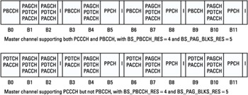
Figure 4.3: Master channel configuration example on downlink.
On master PDCHs that do not carry PBCCH, the first BS_PBCCH_BLKS blocks of the list are used for PDTCHs and PACCHs. The mapping of the other PPCHs, PAGCHs, PACCHs, and PDTCHs remains the same as on the master PDCH carrying PBCCH. The second part of Figure 4.3 shows an example of this configuration with BS_PBCCH_RES and BS_PAG_BLKS_RES parameters equal respectively to 4 and 5.
A downlink slave configuration contains the following packet data logical channel combination: PDTCH + PACCH + PTCCH. A PDTCH or PACCH block may occur on any radio block. Data transfer is carried on PDTCH while signaling is carried on PACCH.
4.1.2 Channel Coding
4.1.2.1 PDTCH
Four coding schemes, CS-1 to CS-4, are used for the GPRS PDTCHs. They offer different levels of protection, and the CS to be used is chosen by the network according to the radio environment. If, for instance, the carrier to interference ratio (C/I) is high, low protection is applied, to achieve a higher data rate, and if the C/I is low, the level of protection is increased, which leads to a lower data rate. This mechanism is called link adaptation.
Coding schemes CS-1 to CS-4 are mandatory for MSs supporting GPRS, but with the exception of CS-1 they may not be supported by the network. Figures 4.4 and 4.5 show the coding principle of one radio block for CS-1 to CS-3 and CS-4, respectively. On the bottom parts of the figures are represented the four NBs on which the block is mapped; each one is transmitted in one TDMA frame.
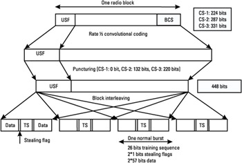
Figure 4.4: Radio block encoding for CS-1 to CS-3.
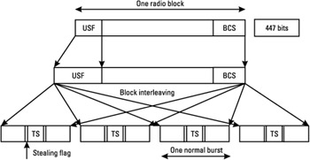
Figure 4.5: Radio block encoding for CS-4.
The first step of the coding procedure consists of adding a block check sequence (BCS) coded on 16 bits for error detection. For CS-2, CS-3, and CS-4, the next step is the precoding of the USF field. The 3-bit field is mapped onto a 6-bit word in CS-2 and CS-3, and on a 12-bit word in CS-4. The USF is used as a token for uplink multiplexing. It needs to be decoded with a very low error rate, by the different mobiles allocated on the same PDCH. That is why its coding is more robust than the rest of the block.
For CS-1, CS-2, and CS-3, the next step involves adding four tail bits prior to a rate 1/2 convolutional encoding stage for error correction. This code is punctured to give the desired coding rate. The same convolutional code is used for the three coding schemes (see Table 4.1) but with a different puncturing rate. The interest of the puncturing is to allow different coding rates with the same convolutional code. It consists on not transmitting some of the bits that are output by the encoder. At the reception, the hole positions are known by the receiver. They are filled with zero before the decoding. For CS-4, there is no convolutional coding. Note that after the convolutional encoding stage, the 3-bit USF field is mapped on a 12-bit word in CS-2, CS-3 (as it is in CS-4), and on a 6-bit word in CS-1.
|
Coding Schemes |
Polynomials |
Code Rate |
|---|---|---|
|
CS-1, CS-2, and CS-3 |
G0 = D4 + D3 + 1 G1 = D4 + D3 + D + 1 |
1/2 |
The coded data obtained (456 bits) is then interleaved over four bursts. The burst format is the NB, as described in Chapter 1.
In GSM, along with each block of 456 coded bits there is a stealing flag (SF) pattern, indicating whether the block belongs to the TCH or to the FACCH. As the FACCH is not used in GPRS, the SFs, at the extremities of the 26-bit TS code, are used to signal the coding scheme used for the block. With the SFs (sequence of 8 bits in a radio block, with 2 bits in each burst), the receiver is able to detect which coding scheme is used for that block, with the correspondence as shown in Table 4.2. Note that the MS always transmits with a CS commanded by the network, whereas in downlink it performs an SF detection prior to the decoding of the block.
|
Coding Scheme |
Stealing Flag Pattern |
|---|---|
|
CS-1 |
11111111 |
|
CS-2 |
11001000 |
|
CS-3 |
00100001 |
|
CS-4 |
00010110 |
Table 4.3 summarizes the characteristics of the different coding schemes. CS-1 uses the same coding scheme as specified for SACCH in GSM. The data rate includes the RLC/MAC header and RLC information.
|
Scheme |
Code Rate |
USF |
Precoded USF |
Radio Block Excluding USF and BCS |
BCS |
Tail Bits |
Coded Bits |
Punctured Bits |
Data Rate (Kbps) |
|---|---|---|---|---|---|---|---|---|---|
|
CS-1 |
1/2 |
3 |
3 |
181 |
40 |
4 |
456 |
0 |
9.05 |
|
CS-2 |
≈2/3 |
3 |
6 |
268 |
16 |
4 |
588 |
132 |
13.4 |
|
CS-3 |
≈3/4 |
3 |
6 |
312 |
16 |
4 |
676 |
220 |
15.6 |
|
CS-4 |
1 |
3 |
12 |
428 |
16 |
- |
456 |
- |
21.4 |
Link Adaptation
The basic principle of link adaptation is to change the coding scheme according to the radio conditions. When the radio conditions get degraded, a more protected CS (more redundancy by reduction of the overall code rate) is chosen, leading to a lower throughput. In contrast, when the radio conditions become better, a less protected CS is chosen, leading to a higher throughput. The radio conditions are determined by the network based on the measurements performed by the MS and the BTS.
The way the "used CS" is signaled by the transmitter to the receiver (in-band signaling by the SFs, as described above) allows the transmitter to adapt its transmission rate without notifying the receiver.
Depending on the radio conditions (Doppler shift due to the mobile speed, multipath, interference) in which the MS operates, the network modifies its transmission rate (CS change) in downlink and orders the use of another CS to the mobile in uplink. The ordered CS for use in uplink is sent within RLC/MAC control messages on the PACCH.
The network evaluates the radio conditions based on quality and received level measurements either performed by the mobile and reported to the network (downlink transfer) or performed by the network (uplink transfer).
4.1.2.2 PCCCH Channel Coding
For all GPRS packet control channels other than PRACH and PTCCH on uplink, the coding scheme CS-1 is always used.
For ABs on PRACH, two coding schemes are defined:
-
Packet AB that carries 8 information bits, the coding of which is the same as for GSM;
-
Extended packet AB that carries 11 information bits. The coding is the same as for the normal AB except that puncturing is used to increase the information field (which slightly decreases the performance).
The extended AB carries more information, which allows the mobile to give more information when requesting the establishment of a TBF. The use of normal AB or extended AB is controlled by the network parameter ACCESS_BURST_TYPE broadcast on BCCH or PBCCH.
4.1.2.3 PTCCH Channel Coding
The PTCCH downlink channel coding is the same as for the GSM SACCH. In uplink, either packet ABs or extended packet ABs are sent depending on the network parameter ACCESS_BURST_TYPE. The information field is set to a fixed pattern.
4.1.3 Power Control
The power control mechanism allows for the adjustment of the radio transmitter output power in order to minimize the interference caused by the transmitter, while maintaining a good radio link quality. In GPRS, power control is used on the uplink and also on the downlink.
4.1.3.1 Uplink Power Control
The uplink power control can be performed in two ways. Either it is managed autonomously by the mobile, in which case the procedure is called open-loop power control, or it is partly controlled by the network, in which case it is called closed-loop power control.
Open-loop uplink power control relies on received power measurements (RXLEV) performed by the mobile on its serving cell. For this mode it is assumed that the path loss is the same in uplink and in downlink. The output power is therefore derived from the RXLEV: the higher the RXLEV, the lower the transmit power.
In closed-loop power control, the network can control either fully or partially the output power that is used by the mobile. The power control in this case can rely on RXLEV measurements performed by the MS on the downlink path or RXLEV and RXQUAL measurements performed by the network on the uplink path, or both types of measurements.
The MS calculates the RF output power value, Pch, to be used on each individual uplink PDCH assigned to the MS with the following equation:
| (4.1) |
where Γch is a parameter specific to the MS and to the PDCH, given to the MS in an RLC control message, Γ0 is a constant parameter that is frequency band dependent, α is a parameter in the range [0,1], Pmax is the maximum output power allowed in the cell, and C is the average received signal level. Pmax is broadcast by the network; Γch and α are parameters that are sent to the MS in dedicated signaling messages.
Equation (4.1) can be rewritten in the following way:
| (4.2) |
with Pch limited to Pmax.
Open-Loop Uplink Power Control
The open loop corresponds to the case where α is set to 1 and β has a constant value; α and β are set during the TBF establishment and are not modified during the TBF. The MS output power is directly deduced from the average received signal level C. Figure 4.6 gives an example of the variation of the output power during time depending on the average received signal level. Note that the output power is limited to Pmax.
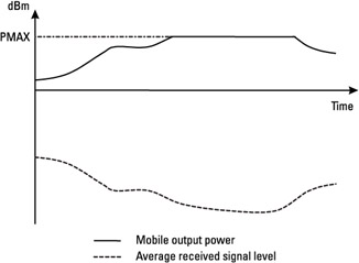
Figure 4.6: Example of uplink power control in open loop.
Closed-Loop Uplink Power Control
As described above, in closed-loop mode, the network can control the computed mobile output power. This control is performed through the sending of the parameters Γch and α during the packet transfer. In case of pure closed-loop mode, the parameter α is set to 0 by the network and the MS output power is directly controlled by the network with the Γch parameter (4.3). In this case the network performs uplink measurements (RXLEV, RXQUAL) and deduces the output power that must be applied by the mobile. One Γch value is sent to the MS for each PDCH to control the computed power.
| (4.3) |
More complicated algorithms that control the output power with both the Γch and α parameters can be implemented in the network.
Received Signal Level Averaging Process
In packet transfer mode, the mobile may perform its measurements on the BCCH or on one allocated PDCH. The PC_MEAS_CHAN parameter broadcast by the network indicates on which type of channel the mobile must perform its measurements. When downlink power control is used by the BTS, the measurements must be performed on the BCCH.
The received signal level is averaged through a recursive filtering that is given by (4.4).
| (4.4) |
Cn represents the average received signal level at the nth iteration, F is the forgetting factor of the recursive filter, and SSn is either the received signal level averaged over the four bursts that compose the block when the measurements are performed on paging blocks or PDCH, or the received signal level of the measurement sample when the measurements are performed on the BCCH carrier.
F is a parameter that is broadcast by the network. Its value can be different depending on the RR state of the mobile and on the channel on which the measurements are performed. A summary of the parameters and their use is presented in Table 4.4.
|
Parameters |
Transmission Mode of Parameters |
Usage |
|---|---|---|
|
Pmax |
Broadcast on BCCH or PBCCH |
Maximum output power allowed in the cell |
|
Γch |
In dedicated signaling |
Closed-loop control parameter different on PDCH basis |
|
α |
Broadcast on BCCH or PBCCH and in dedicated signaling |
Used to control trade-off between open- and closed-loop power control |
|
TAVG_T |
Broadcast on BCCH or PBCCH |
Used to compute forgetting factor F in packet transfer mode. |
|
PC_MEAS_CHAN |
Broadcast on BCCH or PBCCH |
Used to order measurement on the BCCH or PDCH during packet transfer mode |
4.1.3.2 Downlink Power Control
Downlink power control is optional on the BTS side. The operations are different according to the logical channel (see Table 4.5):
-
The BTS must use constant output power on the PDCH that carries PBCCH or PCCCH. The power level used on those PDCHs can be lower than the one used on BCCH. This power level difference is broadcast by the network (Pb parameter).
-
The output power on the PTCCH downlink is constant and is the same as on PBCCH or BCCH if PBCCH does not exist in the cell.
-
On the other PDCH radio blocks, downlink power control can be used. This mechanism is based on the channel quality reports send by the mobile. The network must use the same output power for the four bursts that compose one radio block.
|
Logical Channel Type |
Downlink Power Control Used |
Presence of PBCCH |
BTS Output Power |
|---|---|---|---|
|
PBCCH/PCCCH |
- |
- |
BCCH output power - Pb |
|
PTCCH |
- |
Yes |
BCCH output power - Pb |
|
- |
No |
BCCH output power |
|
|
PDTCH |
Yes |
- |
Any power level that respects the rules described later in section |
|
No |
Yes |
BCCH output power- Pb or no transmission |
|
|
No |
BCCH output power or no transmission |
When downlink power control is used, the BSS must ensure that the output power is sufficient for the MS for which the RLC block is intended as well as the MS for which the USF is intended when operating in dynamic or extended dynamic allocation. Indeed, the RLC block can be addressed to a given mobile, but with a USF field intended for another, as shown in Figure 4.7.
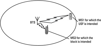
Figure 4.7: Downlink power control for a block addressed to two different mobiles.
Two modes of downlink power control have been defined in order to limit the variations on the BTS transmit power and to allow operation with standard implementation of automatic gain control (AGC) in the mobile (see Section 4.3.5.3).
-
Power control mode A can be used with any allocation scheme;
-
Power control mode B is intended for fixed allocation only.
The BTS power control mode is indicated during the TBF resource assignment by the parameter BTS_PWR_CTRL_MODE.
Both modes use the parameter P0, defined as a power reduction (PR) relative to BCCH output power. This parameter is included in the assignment message. BCCH level - P0 corresponds to the initial BTS output power when the network starts the downlink transfer. The mobile is therefore able to evaluate roughly the received level at the beginning of the transfer from the received level on BCCH. It uses this estimate for the setting of its AGC at the start of the transmission.
Power Control Mode A
In BTS power control mode A, the BTS limits its output power on blocks addressed to a particular MS to levels between (BCCH level - P0) and (BCCH level - P0 -10 dB). The BTS can change its output power from time slot to time slot within the same TDMA frame. The power level of blocks not addressed to the mobile does not have to exceed BCCH level - P0.
Figure 4.8 shows an example of BTS output power limitations. In this example, the first four time slots (TSs) are allocated to a multislot mobile.
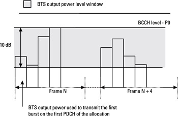
Figure 4.8: Example of downlink power control mode A.
Power Control Mode B
In power control mode B, the BTS may use its full output power range (i.e., 30 dB). It uses the same output power on all blocks addressed to a particular MS within a TDMA frame. The BTS changes the output power no faster than one nominal power control step (2 dB) every 60 ms.
Moreover, when the BTS addresses a block to a particular mobile M1 and the block that is transmitted on the previous time slot is addressed to another mobile M2, if the block that is addressed to M2 is transmitted on a PDCH that is part of the M1 allocation, its transmit output power shall not exceed the transmit output power of the block that is addressed to M1 by more than 10 dB.
This is summarized in Figure 4.9, where the first four bursts of the TDMA frame (one TDMA frame = 8 TS) are represented, because they correspond in the example to the PDCH allocation of a given mobile. The block that is represented in gray on the figure is dedicated to another MS, and can therefore be sent with a different level, that can be up to 10 dB higher, as explained above.
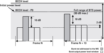
Figure 4.9: Example of downlink power control mode B.
PR Management
When downlink power control is used, the BTS may indicate, for some PDCH downlink blocks, the output power level used to send these blocks. This level is indicated by the PR field if present in the block. It gives the power level reduction used to send this block relative to BCCH level-P0.
Two PR management modes have been introduced: PR mode A and PR mode B. The PR mode is indicated during the assignment phase with the PR_MODE parameter. In PR mode A, the PR field of a block is calculated based on the BTS output power level in the direction of the addressed (RLC information) MS. This mode is suited for the case of adaptive antennas (the transmitted power is not the same in the different directions, and therefore an MS for which the block is not addressed cannot use the PR field). In PR mode B, for each block sent on a given PDCH, the BTS uses the same output power level for all the MSs with TBF on this PDCH. Since the PR field can be interpreted by all the mobiles, this mode cannot be used with adaptive antennas.
The network is not allowed to change the PR mode during a TBF. The information fields PR, P0, PR_mode, and BTS_PWR_CTRL_MODE may be used by the MS for its AGC algorithm.
Table 4.6 lists the parameters that are involved in the downlink power control procedure.
|
Parameters |
Transmission Mode of Parameters |
Usage |
|---|---|---|
|
BTS_PWR_CTRL_MODE |
During resource assignment |
BTS downlink power control mode used on network side |
|
PR_MODE |
During resource assignment |
PR mode associated with power control |
|
P0 |
During resource assignment |
Used to indicate the initial output power of the BTS |
|
PR |
RLC/MAC block |
Power level reduction used to send the radio block |
|
Pb |
Broadcast on BCCH or PBCCH |
Power level reduction of PBCCH and PCCCH compared to BCCH |
4.1.4 MS Measurements
The measurements performed by the MS are described in Section 3.3.1.5. The network may request the mobile to perform measurements in packet idle mode for reasons other than reselection. These measurements are used by the network operator for frequency planning, and may be of two types:
-
Power measurements on an additional frequency list;
-
Interference measurements on an additional frequency.
4.1.4.1 Extended Measurements
The network broadcasts a list of frequencies to be measured for extended measurements. A reporting period is indicated by the network to describe the periodicity of the MS reports.
4.1.4.2 Interference Measurements
The network may request the mobile to perform interference measurements. These measurements involve estimating the received level on a PDCH that is not necessarily a broadcast channel. They are performed on different channels depending on the RR state:
-
In packet idle mode-on a list of carriers broadcast by the network;
-
In packet transfer mode-on the same carrier as the assigned PDCH.
The MS measures the received signal level during its idle frames, on a carrier allocated in its serving cell, to estimate the interference level due to neighbor cells. It may happen that the measurement is performed when a signal is transmitted in the MS cell, leading to a wrong estimation of the interference level due to neighbor cells. For instance, this signal may be a GSM SACCH block (as the structure of a 52-multiframe is the juxtaposition of two 26-multiframes) or a GPRS PTCCH occurrence-if the TA update procedure is used on this channel (see Figure 4.10).
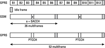
Figure 4.10: Collision between idle frames and SACCH frames or PTCCH frames.
The MS performs at least one interference measurement on a number of TSs, which is equal to the maximum number of receive TSs according to its multislot class. An instantaneous interference value is obtained for each time slot. In order to decorrelate the estimation from the signaling blocks (SACCH and PTCCH) from its own cell, it performs the measurement on at least two consecutive idle frames. Only the lowest measured level is kept, so that the signal measurement on the serving cell can be discarded. The received signal level samples SSch,n on the PDCH are then averaged with a running average filter:
| (4.5) |
where γch,n is the measured interference level, d is the forgetting factor, and n is the iteration index.
The interference measurements are not reported in packet idle mode but are reported in packet transfer mode in case of network request. For each time slot where interference measurements are performed, a running average γch,n value is reported.


