Case Studies
6.6 Case Studies
6.6.1 Establishment of a BVC
This section describes the procedure for a BVC establishment between the SGSN and the BSS. The procedure is described in Figure 6.32. It is triggered by O&M. For each cell in the BSS supporting GPRS service, a BVC must be established between the BSS and the SGSN in order to exchange GPRS traffic.
 Figure 6.32: BVC establishment procedure.
The establishment procedure is only possible if at least one NS-VC at NS layer, belonging to the same NSE of the cell, already exists and is operational. The BSS starts the establishment of the BVC by triggering a BVC reset procedure. At the end of the procedure the BVC is in the UNBLOCKED state.
Once the BVC has been established, the BSS must indicate the amount of memory available for the BVC for flow control between the SGSN and the BSS. This will allow downlink traffic on the BVC. Thus the BSS triggers a BVC flow control procedure indicating bucket parameters necessary for initiating the flow control procedure. The basic flow control procedure is repeated in a periodic way (controlled by the Tflow timer in the figure).
Note that as described in Section 6.5.4.4, at the end of a successful BVC reset procedure, the BVC is in the UNBLOCKED state. If the BSS does not want to allow the traffic immediately after the reset procedure, therefore not starting the flow control procedure, it must block the BVC.
Every time the BSS sends a FLOW-CONTROL-BVC message to the SGSN, it must indicate the bucket size Bmax of the BVC and the bucket leak rate R. Bmax must be evaluated so that no underflow condition occurs during downlink transfer because it is undersized. The bucket size Bmax is dependant of the following cell parameters:
-
The number of time slots in the cell that carries GPRS traffic (PDCH);
-
The maximum throughput that can be achieved per PDCH.
Bmax can be computed as follow:
| (6.2) |
where
-
MAXth = Maximum throughput per PDCH. If the network supports CS-1 to CS-4 channel coding, the maximum throughput will be the CS-4 rate.
-
Npdch = Number of PDCHs in the cell.
-
Tflow = Timer that manages the repetition of the flow control procedure.
R is more difficult to evaluate, as its value is dependent on the radio conditions on the air interface. It can be computed as follows:
| (6.3) |
-
(the initial value when the BVC has just been established)
| (6.4) |
-
(the estimated value, taking into account the average throughput per time slot)
where
-
AVth = Evaluated average throughput per time slot.
6.6.2 Downlink Transfer Procedure
This section describes how the transfer of downlink LLC frames within DL-UNITDATA PDUs on the Gb interface is managed when flow control at MS level is used in the BSS. An example of this procedure is described in Figure 6.33.

Figure 6.33: Downlink transfer procedure.
When the SGSN wants to send one DL-UNITDATA PDU that is addressed to one mobile for which no dedicated flow control parameters are available, it will use the default MS bucket parameters that are provided within the FLOW-CONTROL-BVC message.
When the BSS receives the DL-UNITDATA PDU, it starts the MS flow control procedure if it is supported by the BSS. The BSS creates a context for the new mobile and evaluates the bucket size and the bucket leak rate.
The bucket size Bmax depends on the following parameters:
-
The number of time slots (PDCH) that are allocated to the mobile for the downlink transfer;
-
The maximum throughput that can be achieved per PDCH.
Bmax can be computed as follows:
| (6.5) |
where
-
Npdch ms = Number of PDCHs allocated to the mobile for downlink transfer;
-
MAXth = Maximum throughput per PDCH (if the network supports the channel coding scheme CS1 to CS-4, the maximum throughput will be CS-4 rate);
-
Tflow ms = Timer that manages the repetition of the flow control procedure.
The bucket leak rate R depends on the following parameters:
-
The number of mobiles that are multiplexed in downlink on the same PDCHs as the ones allocated to the mobile;
-
The average throughput on the PDCHs. R can be computed as follows:
| (6.6) |  |
-
(the initial value when the BVC has just been established)
| (6.7) |
-
(the estimated value, taking into account the average throughput per TS)
where
-
AVth = Evaluated average throughput per time slot;
-
Nms: = Number of mobiles multiplexed on the same PDCH.
6.6.3 Scenario for Cell Reselection During Downlink Transfer on Gb Interface
This section describes an example of a procedure that can happen when the mobile triggers a cell reselection during a downlink transfer. In this example, the cell reselection occurs between two cells belonging to the same SGSN.
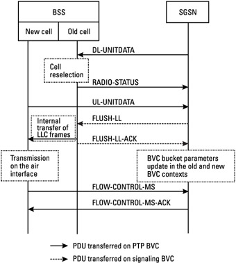
During the downlink transfer, LLC frames that must be sent to the mobile are sent to the BSS in DL-UNITDATA PDUs. During the transfer on the radio interface of one LLC frame, a cell reselection is triggered, either by the network or by the mobile. In the case where it has been triggered by the network, a RADIO-STATUS PDU is sent to the SGSN indicating a "cell reselection ordered" cause. When the cell reselection is triggered by the MS, the network detects a radio interface problem and sends a RADIO-STATUS PDU after the reselection detection.
When the mobile arrives in the new cell, it triggers a cell update procedure. This procedure brings about the sending of an UL-UNITDATA PDU between the BSS and the SGSN that contains the cell update information. The SGSN deduces the new cell in which the mobile is located.
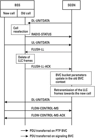
The SGSN then triggers a flush procedure in order to transfer the LLC frames that have not been sent on the air interface toward the new cell in the BSS. This can be the case if the two cells belong to the same NS entity and to the same RA. If not, or if the BSS is not able to transfer internally the LLC frames, they are removed from memory in the BSS. In this case, the SGSN will have to retransmit the deleted LLC frames toward the new cell in the BSS.
For an internal transfer of LLC frames within the BSS, the old cell and the new cell must belong to the same NS entity so that the BVC flow control context for the new cell in the SGSN can be updated. This is only possible by means of the flush procedure, which is internal to an NS entity. The two cells must also belong to the same RA so that the TLLI of the mobile is kept during the cell reselection. The BSS is able to start the downlink transfer of LLC frames on the air interface having the MS identifier.
Figure 6.34 describes the scenario during which the BSS transfers internally the LLC frames from the old cell to the new cell. After this transfer, the BSS sends a FLUSH-LL-ACK PDU in order to indicate that the LLC frames have been transferred and the amount of data impacted. This last parameter is used to adjust the BVC bucket parameter in the old cell context and the new cell context in the SGSN. Once the LLC frames are transferred toward the new cell in the BSS, their transfer on the air interface can start. As soon as the BSS is able to start the downlink transfer, it also triggers the MS flow control procedure in the new cell.

Figure 6.34: Cell reselection between two cells belonging to the same NSE and RA with internal transfer of LLC frames.
Figure 6.35 describes the scenario during which the BSS is not able to transfer internally the LLC frames from the old cell to the new cell. In this case, the BSS deletes the LLC frames within the old cell context and sends a FLUSH-LL-ACK PDU in order to indicate the amount of data that has been deleted. This parameter is used by the SGSN to adapt the BVC bucket parameters in the old cell. The SGSN starts the retransmission of LLC frames that have not been sent on the air interface. At the reception of the first DL-UNITDATA PDU, the BSS starts the MS flow control procedure.

Figure 6.35: Cell reselection between two cells without internal transfer of LLC frames.
There is a great difference in the cell reselection interruption between these two procedures. In fact, in the first example (when the internal transfer of LLC frames is possible within the BSS), the downlink transfer interruption is shorter as the BSS is able to restart the retransmission of LLC frames as soon as the mobile has performed its cell update in the new cell. In the second scenario, the SGSN must retransmit the LLC frames to the BSS before being able to send on the air interface.


