Frame Relay Basics
6.2 Frame Relay Basics
As mentioned previously, the NS layer relies on the frame relay protocol. This section provides a brief background discussion of the protocol. Frame relay is a common protocol that is used in many packet-switched networks.
Frame relay is an evolution of the X25 packet-switched technology. It is based on the concept of virtual circuits (VCs). There are two types of VCs: permanent virtual circuits (PVCs) and those allocated on demand, or switched virtual circuits (SVCs).
The Gb interface relies on the allocation of PVCs only.
PVCs are set up by the network operator via a NM system. They are defined as a connection between two endpoints. They are fixed paths; this means that they are not allocated dynamically or on a per-call basis. Unlike X25, frame relay eliminates all layer 3 processing. Only a few layer 2 functions are used, such as checking for a valid, error-free frame but not requesting transmission if an error is found.
Note that all layer 3 processing has been eliminated due to progress in the reliability of transmission means. As the transmission is extremely reliable, only very few frames are received erroneously; when a frame relay switch receives an erroneous frame, it discards it.
6.2.1 Frame Format
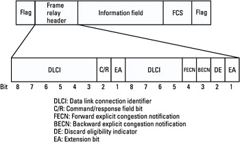
Frame relay uses a variable-length framing structure. This structure is shown in Figure 6.3. Two flags are delimiting the frame. A frame check sequence (FCS) is added for integrity protection.
 Figure 6.3: The FR frame format.
The address field DLCI has a variable length (6- or 10-bit length). The end address (EA) is used to manage the length of the address field. When it is set to 0, the next octet contains the rest of the address; otherwise, it indicates the last field of the address. The C/R bit indicates whether the frame is a command frame or a response frame.
The BECN and FECN bits are used to avoid congestion. They are used when a congestion situation is about to occur in one direction or in the reverse direction. The source endpoint that receives this information will reduce its throughput.
The DE bit allows the network nodes to indicate which frames will be eliminated first in case of congestion, as described in Section 6.2.3.
6.2.2 Addressing
The frame relay header contains a 10-bit field called the data link connection identifier (DLCI). The DLCI is the frame relay VC number (with local significance) that corresponds to a particular destination. It is a number used to distinguish the connection between the endpoint and the frame relay switch from all other connections that share the same physical port.
The DLCI allows data coming into a frame relay switch to be sent across the network using a simple three-step process: First, the integrity of the frame is checked using the FCS. If an error is detected, the frame is discarded (error recovery is performed at a higher level). The incoming DLCI is then looked up in the routing table. The associated outgoing link is identified, together with the outgoing DLCI. The frame is relayed toward its destination by sending on the link specified in the table with the outgoing DLCI.
Figure 6.4 illustrates a frame relay network composed of four FR switches. Between the two end users, a PVC is established. The arrow shows the commutation in each switch and the DLCI associated with each link that is used to define the PVC. DLCI numbers change through the network from switch to switch for the same PVC. They have only local significance for each port.

Figure 6.4: Example of FR network.
6.2.3 Flow Control Mechanism
In severe congestion, the overall network throughput can diminish, and the only way to recover is for the user endpoints to reduce their traffic. For this reason several mechanisms have been developed to notify the user endpoints that congestion is occurring and that they should reduce their offered load.
There are two types of mechanisms to minimize, detect, and recover from congestion situations:
-
Explicit congestion notification;
-
Discard eligibility.
These mechanisms use specific bits contained within the header of each frame. The locations of these specific bits (FECN, BECN, DE) are shown in Figure 6.3.
6.2.3.1 Explicit Congestion Notification Bits
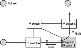
The first mechanism uses two explicit congestion notification (ECN) bits in the frame relay header. They are called the BECN and FECN bits. Figure 6.5 depicts the use of these bits when an FR switch is congested.

Figure 6.5: Explicit congestion notification mechanism.
Let us suppose that the FR switch B in gray in the figure is approaching a congestion condition. This could be caused by a temporary peak in traffic coming into the node from various sources or a peak in the amount of traffic between B and C. Here is how forward congestion notification would occur:
-
FR switch B would detect the onset of congestion based on internal measures such as memory buffer usage or queue length.
-
FR switch B would signal FR switch C of the congestion by changing the FECN contained within the frames destined for FR switch C from 0 to 1.
-
All intermediate downstream nodes as well as the connected user device (source and destination) would thus learn that congestion is occurring on the DLCIs affected.
It is sometimes more useful to notify the source of the traffic that there is congestion, so that the source can slow down until congestion subsides. This is called backward congestion notification.
In our example, FR switch B looks at frames coming in the other direction on the connection. It sets the BECN bit within those frames to signal the upstream nodes and the attached user device.
6.2.3.2 Discard Eligibility
FR standards state that the user device should reduce its traffic in response to a congestion notification. Implementation of the recommended actions by the user device will result in a decrease in the traffic into the network, thereby reducing congestion. However, if the user device is incapable of responding to the signaling mechanisms, it might simply ignore the congestion signal and continue to transmit data at the same rate as before. This would lead to continued or increased congestion.
When congestion occurs, the network must decide which frames to discard. This is done with the DE bit. When the DE bit is set to 1, it makes the frame eligible for discard in situations of congestion. The DE bit is set to 1 by the frame relay switches when the source transmits frames at a rate exceeding the contracted rate.


