NS Layer
6.4 NS Layer
6.4.1 SNS Entity
This section describes the SNS sublayer. This sublayer manages the frame relay protocol and consequently the PVCs. The first section explains whether the BSS or the SGSN will behave as the user or network side, depending on the network configuration. The second section describes the signaling procedures that are used at BSS and SGSN sides to signal the addition or deletion of PVCs and to verify the integrity of the link.
6.4.1.1 Network Configuration
The SNS layer is based on frame relay. In a frame relay network, two kinds of interface can be distinguished: the interface between the user and the network (UNI) and the interface between two FR switches of the same network [network-network interface (NNI)]. The UNI defines the border between one user and the FR network; the NNI defines the communication between two FR switches.
The Gb interface has been defined as a UNI. However, as two configurations are possible, it is necessary each time to define which node behaves as the user and which node behaves as the network. The two configurations are described in Figure 6.9. The first one corresponds to the case in which there is a direct link between the BSS and the SGSN. In this case, the BSS is considered as the user side of the UNI and the SGSN is considered as the network side.
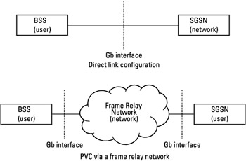 Figure 6.9: Network configurations.
The second configuration corresponds to the case in which the BSS and the SGSN are connected via an intermediate frame relay network. In this configuration, both BSS and SGSN are treated as the user side of the UNI. The NNI is not directly part of the GPRS network and thus is not defined in the GPRS specifications.
6.4.1.2 Signaling Procedure
This section describes the signaling procedures that are implemented at the SNS layer in order to manage the PVCs between the SGSN and the BSS. The link management involves PVCs status monitoring, detection of newly added PVCs, and link integrity verification. The link management interface (LMI) protocol is responsible for these procedures. For GPRS (BSS or SGSN), the protocol is used over the UNI. It is described in [2]. In addition (GPRS standard requirement), it will comply with [3]. The procedures handled by the protocol are as follows:
-
Notification of the addition of a PVC;
-
Detection of the deletion of a PVC;
-
Notification of the availability or unavailability state of a configured PVC;
-
Link integrity verification.
These four procedures are handled using the same set of messages. These messages are the STATUS ENQUIRY and STATUS messages. They are sent on DLCI = 0, which identifies signaling.
The STATUS ENQUIRY message is sent to request the status of PVCs or to verify link integrity. It is always sent by the user (the BSS in case of direct link configuration, the BSS and the SGSN otherwise; see previous section). The STATUS message is sent in response to a STATUS ENQUIRY message to indicate the status of PVCs or for link integrity verification.
The status of the PVC connection and the verification of the link integrity are managed using a periodic polling mechanism. This involves periodically requesting, for each user, the link status. Figure 6.10 describes the basic status procedure.
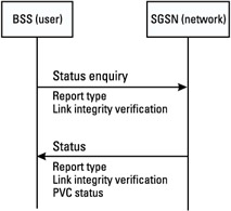
Figure 6.10: Basic status procedure.
The STATUS ENQUIRY message is composed of:
-
The report type indicating the purpose of the message sending. This can be either the request of a full link status or link integrity verification only. When a full link status is requested, the network side indicates the newly added PVCs, the deleted PVCs, and the state of each PVC, and a link integrity verification is performed.
-
The link integrity verification parameters. These parameters are described later in this section.
The STATUS message is composed of the report type (indicating either full status or link integrity verification only), the link integrity verification parameters, and the PVCs' status indicating the status of existing PVCs on the BC when it has been requested in the STATUS ENQUIRY message.
Periodic Polling
The user equipment (BSS if there is no intermediate FR network; BSS and SGSN otherwise) always initiates the polling (status enquiry). The polling procedure involves requesting link integrity verification in a periodic way and requesting a full PVC status every N polling cycles (see Figure 6.11). Every N expiries of the timer that controls link integrity verification, the full STATUS ENQUIRY message is sent; the other N - 1 expiries trigger the sending of the "link integrity verification only" STATUS ENQUIRY message.
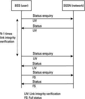
Figure 6.11: Periodic polling procedure.
In response to a full status request, the network sends a STATUS message containing a PVC status information element for each PVC configured on that BC. Each information element contains an active bit indicating the availability or unavailability of that PVC. When a PVC is detected as nonactive, the user equipment stops transmitting frames on the PVC until the PVC becomes active again. When the user receives a full status message containing a PVC status information element identifying an unknown DLCI and indicating a new PVC, the user equipment marks this PVC as new.
Link Integrity Verification
The purpose of the link integrity verification is to allow both sides of the UNI to determine the status of the in-channel signaling link (DLCI 0). This is necessary, since these procedures use unnumbered information (UI) frames; these frames are not acknowledged between the peer entities.
For the link integrity verification procedure, each side of the UNI maintains one receive sequence counter (RSC) and one send sequence counter (SSC). Every time a STATUS ENQUIRY or STATUS message is sent, the values of these counters are included in the message by the sending side. The field send sequence number (SSN) within the message indicates the value of the SSC, and the receive sequence number (RSN) indicates the value of the RSC.
The SSC indicates the number of STATUS ENQUIRY or STATUS messages that have been sent. The RSC indicates the number of STATUS ENQUIRY or STATUS messages that have been received.
Before sending a STATUS ENQUIRY message, the user side increments its SSC counter. When the network side receives the STATUS ENQUIRY message, it compares the RSN received within the message with its own SSC. The number of messages that have been received at one side will be equal to the number of messages that have been sent from the other side.
The received SSN is stored in the RSC. The network side increments its SSC counter and sends the STATUS message. At the reception of the STATUS message, the user side compares the RSN received with its own SSC. Whenever the SSC and the RSN values do not match, a message has been lost on the interface and the integrity of the link is not verified.
Figure 6.12 gives an example of the link integrity verification procedure. When the BSS receives the STATUS message, it compares the number of STATUS ENQUIRY messages that have been received at the SGSN side (RSN = 1) with the number of STATUS ENQUIRY messages that it has sent (SSC = 1). The number of STATUS messages received is then equal to the number of STATUS messages sent by the SGSN (RSC is set to SSN).
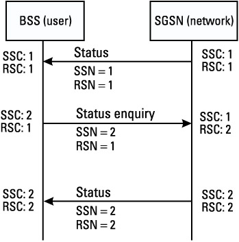
Figure 6.12: Example of successful link integrity verification procedure.
Before sending a new STATUS ENQUIRY message, the BSS increments its SSC counter. The comparison of the number of STATUS ENQUIRY messages received and sent by the BSS is then performed at SGSN side.
6.4.2 NSC Entity
The NSC sublayer is responsible for the management of the NS-VCs between the BSS and the SGSN and the transfer of upper-layer packets. This section details the procedures that are used at NSC layer for the transfer of upper-layer data and the procedures that are used for the management of the NS-VCs.
6.4.2.1 Upper-Layer Packet Transfer
The NS-UNITDATA message is used to transfer upper-layer packets or SDUs that are encapsulated inside. This message is sent across the Gb interface in unacknowledged mode. The same message is used for transfer from the BSS to the SGSN or from the SGSN to the BSS (see Figure 6.13). The NS-UNITDATA message contains the SDU to be transmitted and the BVCI identifying the addressed BVC.

Figure 6.13: NS-PDUs transfer.
6.4.2.2 NS-VC Management
The NSC sublayer is responsible for the management of NS-VCs. These are statically configured by O&M means.
One NS-VC can be in one of the following three states:
-
DEAD. In this state end-to-end communication between the peer NS entities does not exist.
-
BLOCKED & ALIVE. In this state the NS-UNITDATA are not allowed to transit across the NS-VC. This could be due to an O&M intervention or equipment failure.
-
UNBLOCKED. In this state NS-UNITDATA are accepted and can be sent.
Figure 6.14 describes the NS-VC state transition. After a successful reset procedure, the NS-VC state is BLOCKED & ALIVE. The transition from the BLOCKED state to the UNBLOCKED state and the reverse transition are managed by the unblocking and blocking procedures, respectively. As soon as an NS-VC has been reset (the NS-VC is in BLOCKED or UNBLOCKED state), a periodic test procedure is triggered to regularly verify its availability.
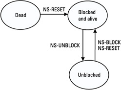
Figure 6.14: NS-VC state transition within the BSS and SGSN.
NS-VC Reset
This procedure is used when a new NS-VC is set up, after a processor restart, a failure recovery, or any local event restoring an existing NS-VC in DEAD or undetermined state.
At the end of the procedure, a successful reset NS-VC is marked as BLOCKED and ALIVE. The initiator of the procedure must trigger the periodic test procedure.
This procedure may be initiated by the SGSN or by the BSS. Figure 6.15 shows an example of NS-VC reset initiated by the BSS. The BSS sends an NS-RESET message to the SGSN. This message indicates the cause of the reset procedure, the NSEI, and NS-VCI identifying the NS-VC to be reset. The NS-VC is then marked as BLOCKED and DEAD within the BSS. When the SGSN receives the NS-RESET message and if it is able to reset the NS-VC, it returns an NS-RESET-ACK message indicating the NS-VCI and NSEI identifying the NS-VC that has been reset. This message is sent on the NS-VC that has been reset. The NS-VC is marked as BLOCKED and ALIVE at SGSN side. When the BSS receives the NS-RESET-ACK message, it marks the NS-VC as BLOCKED and ALIVE and it initiates the test procedure. After the reset of an NS-VC, the unblocking procedure of the NS-VC is triggered by the originator of the reset procedure.
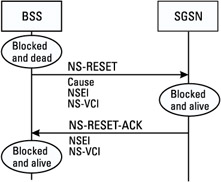
Figure 6.15: Reset procedure.
Blocking/Unblocking of an NS-VC
The blocking/unblocking procedures are used in case of failure in the transmission network, O&M intervention, or equipment failure. These procedures can be triggered either by the SGSN or the BSS.
Blocking Procedure Figure 6.16 shows an NS-VC blocking procedure triggered by the SGSN. Once the decision to block an NS-VC has been made, the SGSN (in the example) marks the NS-VC as BLOCKED. The NS-UNITDATA messages will be redistributed to other UNBLOCKED NS-VCs belonging to the same NSE, thanks to the load-sharing function (see Section 6.4.2.3).
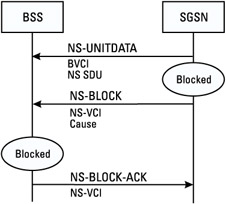
Figure 6.16: Example of blocking procedure initiated by the SGSN.
The NS-BLOCK message is sent by the SGSN. It contains the NS-VCI of the NS-VC to be blocked. The NS-BLOCK message can be sent in any alive NS-VC pertaining to the NSE. The SGSN will continue to accept NS-UNIDATA messages until it receives the NS-BLOCK-ACK PDU indicating the NS-VC blocking.
On the BSS side, at the reception of the NS-BLOCK message, the NS-VC is marked as BLOCKED in the BSS. The NS user entity is informed and NS-UNITDATA messages are redistributed to other UNBLOCKED NS-VCs. The NS-BLOCK-ACK message is sent in any ALIVE NS-VC pertaining to the same NSE.
Unblocking Procedure Figure 6.17 shows an NS-VC unblocking scenario triggered by the BSS. The BSS triggers the unblocking of an NS-VC by sending an NS-UNBLOCK message on the concerned NS-VC. For this the NS-VC will be in the ALIVE state (see the following section). When the SGSN receives the NS-UNBLOCK message and if it is able to unblock the NS-VC, it returns an NS-UNBLOCK-ACK message on the same NS-VC. The NS-VC state is changed to UNBLOCKED. The load-sharing function and the NS user entity are informed. In the BSS, the state of the NS-VC is changed at the reception of the NS-UNBLOCK-ACK PDU.
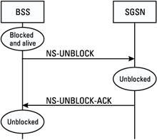
Figure 6.17: Example of unblocking procedure between the SGSN and the BSS.
NS-VC Test
The test procedure is used when one NSC entity wishes to check that end-to-end communication with its peer entity exists on an NS-VC. This procedure is triggered at the end of a successful reset procedure by the originator of the reset procedure and is periodically repeated. The procedure can be initiated by the BSS or the SGSN, depending on the originator of the reset procedure.
Figure 6.18 illustrates a test procedure initiated by the SGSN. On receipt of the NS-RESET-ACK message, the originator (SGSN) of the reset procedure starts a timer (Ttest) managing the periodical repetition of the test procedure. When this timer expires, the originator sends an NS-ALIVE message on the NS-VC to be checked. Upon receipt of the NS-ALIVE message on an ALIVE NS-VC, the BSS returns an NS-ALIVE-ACK message on the same NS-VC. Upon receipt of the NS-ALIVE-ACK message, the SGSN restarts the timer managing the repetition of the test procedure.
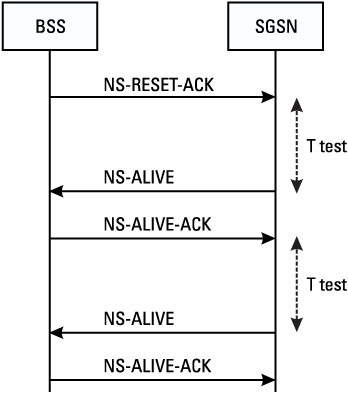
Figure 6.18: Test procedure initiated by the SGSN.
Note that when a failure in the test procedure is detected, it is restarted. After several failures of the test procedure, the NS-VC is marked as BLOCKED and a blocking procedure is triggered.
6.4.2.3 Load Sharing
The load-sharing function of an NSE receives as input the NS SDUs from all the BVCs belonging to this NSE (see Figure 6.19). It is responsible for the NS SDU traffic repartition between the NS-VCs belonging to this NSE. It provides to the upper layer a seamless service upon failure. In fact, in such a case, it reorganizes the NS SDU traffic between the UNBLOCKED NS-VCs of the same NSE. This procedure is implemented at both the BSS and SGSN sides. Upon reorganization of the traffic, the order of NS SDU transfer may be disturbed.
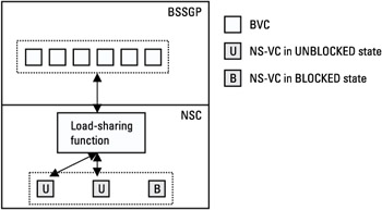
Figure 6.19: Load-sharing function.
All NS SDUs to be transmitted over Gb are passed to the load-sharing function along with the link selector parameter (LSP), the BVCI, and the NSEI. The LSP and BVCI are used to select the UNBLOCKED NS-VCs within the group. For each BVCI and NSEI, the selection of the NS-VC is based on the LSP. For each BVCI and NSEI, NS SDUs with the same LSP will be sent on the same NS-VC. The load-sharing function guaranties that for each BVC, the order of all NS SDUs marked with the same LSP value is preserved.
Note that on the Gb interface, upper-layer SDUs for the same mobile must be transferred in order. The LSP is a parameter, implementation dependent, that is used to guaranty this. In the SGSN, as each mobile is uniquely identified by its TLLI, it could be possible to use the TLLI as the LSP parameter. This will guaranty ordered transfer for each mobile.


