Collaboration Diagrams
Collaboration Diagrams
The second form of the interaction diagram is the collaboration diagram.
Within a collaboration diagram, the example objects are shown as icons. As on a sequence diagram, arrows indicate the messages sent within the given use case. This time, however, the sequence is indicated by numbering the messages.
Numbering the messages makes it more difficult to see the sequence than putting the lines down the page. On the other hand, the spatial layout allows you to show other things more easily. You can show how the objects are linked together and use the layout to overlay packages or other information.
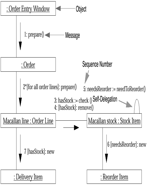
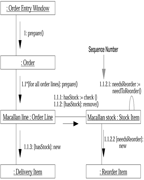
You can use one of several numbering schemes for collaboration diagrams. The simplest is illustrated in Figure 5-4. Another approach involves a decimal numbering scheme, seen in Figure 5-5.
Figure 5-4. Collaboration Diagram with Simple Numbering

Figure 5-5. Collaboration Diagram with Decimal Numbering

In the past, most people used the simple numbering scheme. The UML uses the decimal scheme because it makes it clear which operation is calling which other operation, although this makes it harder to see the overall sequence.
Regardless of what numbering scheme you use, you can add the same kind of control information you might show on a sequence diagram.
In Figure 5-4 and Figure 5-5, you can see the various forms of the UML's object naming scheme. This takes the form objectName : ClassName, where either the object name or the class name may be omitted. Note that if you omit the object name, you must retain the colon so that it is clear that it is the class name and not the object name. So the name "Macallan line : Order Line" indicates an instance of Order Line called Macallan line (this is an order I would particularly appreciate). I tend to name objects in the Smalltalk style that I used in the sequence diagrams. (This scheme is legal UML because "anObject" is a perfectly good name for an object.)


