Chapter 9. Activity Diagrams
Chapter 9. Activity Diagrams
Activity diagrams are one of most unexpected parts of the UML.
Unlike most other techniques in the UML, the activity diagram doesn't have clear origins in the previous works of the three amigos. Rather, the activity diagram combines ideas from several techniques: the event diagrams of Jim Odell, SDL state modeling techniques, workflow modeling, and Petri nets. These diagrams are particularly useful in connection with workflow and in describing behavior that has a lot of parallel processing.
I'm going to describe activity diagrams in more detail than they really warrant in this short book. The reason is that they are one of the least understood areas of the UML, and current UML books are particularly lacking in discussing them.
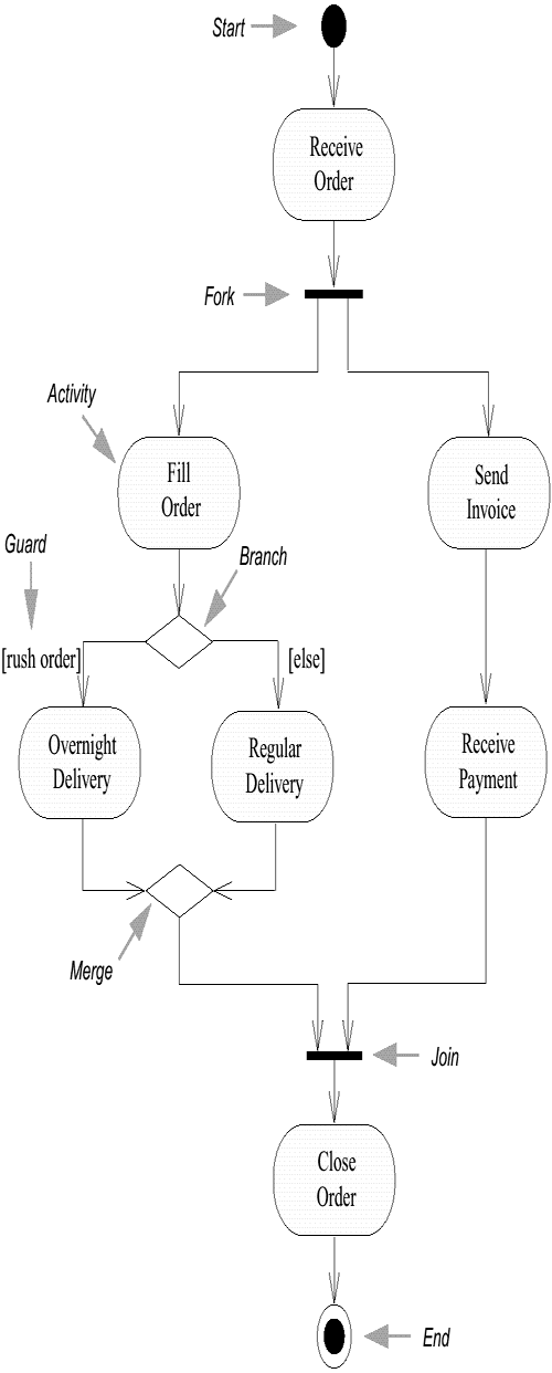
In Figure 9-1, the core symbol is the activity state, or simply activity. An activity is a state of doing something: either a real-world process, such as typing a letter, or the execution of a software routine, such as a method on a class.
Figure 9-1. Activity Diagram

The activity diagram describes the sequencing of activities, with support for both conditional and parallel behavior. An activity diagram is a variant of a state diagram in which most, if not all, the states are activity states. Thus, much of the terminology follows that of state diagrams.
Conditional behavior is delineated by branches and merges.
A branch has a single incoming transition and several guarded outgoing transitions. Only one of the outgoing transitions can be taken, so the guards should be mutually exclusive. Using [else] as a guard indicates that the "else" transition should be used if all the other guards on the branch are false.
In Figure 9-1, after an order is filled, there is a branch. If you have a rush order, you do an overnight delivery; otherwise, you do a regular delivery.
A merge has multiple input transitions and a single output. A merge marks the end of conditional behavior started by a branch.
You don't have to show the explicit diamond for branches and merges. An activity state, like any state, can have multiple guarded output transitions and multiple input transitions. Use diamonds if you want to make the branches and merges clear in the diagram.
Parallel behavior is indicated by forks and joins.
A fork has one incoming transition and several outgoing transitions. When the incoming transition is triggered, all of the outgoing transitions are taken in parallel. Thus, in Figure 9-1, after you receive an order, you fill the order and send the invoice in parallel.
The diagram says that these activities can occur in parallel. Essentially, this means that the sequence between them is irrelevant. I could fill the order, send the invoice, deliver, and then receive payment; or, I could send the invoice, receive the payment, then fill the order and deliveryou get the picture.
I can also do these activities by interleaving. I grab the first line item from stores, type up the invoice, grab the second line item, put the invoice in an envelope, and so forth. Or, I could do some of this simultaneously: type up the invoice with one hand while I reach into my stores with another. Any of these is correct, according to the diagram.
The activity diagram allows me to choose the order in which to do things. In other words, it merely states the essential sequencing rules I have to follow. This is the key difference between an activity diagram and a flowchart: flowcharts are normally limited to sequential processes, whereas activity diagrams can handle parallel processes.
This is important for business modeling. Businesses often have unnecessarily sequential processes. A technique like this that encourages parallel behavior is valuable in these situations because it encourages people to move away from unnecessary sequences in their behavior and to spot opportunities to do things in parallel. This can improve the efficiency and responsiveness of business processes.
Activity diagrams are also useful for concurrent programs, since you can graphically lay out what threads you have and when they need to synchronize.
When you get parallel behavior, you need to synchronize. We don't close the order until it is delivered and paid for. We show this with the join before the Close Order activity. With a join, the outgoing transition is taken only when all the states on the incoming transitions have completed their activities.
Forks and joins must match. In the simplest case, this means that every time you have a fork, you must have a join that joins together the threads started by that fork. (This rule comes from the fact that the activity diagram is presently a form of state diagram.)
However, there are several extensions to this rule.
A thread that comes out of a fork can itself fork, with the new threads coming back together before reaching the matching join.
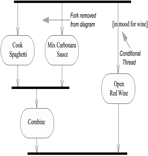
If a thread coming out of a fork goes straight into another fork, you can remove the second fork and just have the threads from the second fork coming out of the first fork. Thus, in Figure 9-2, I have removed a fork between the food preparation activities and the opening fork. Similarly, if a join goes right into another join, you can eliminate the first join and have the threads go right into the second join. This is a notational shorthand to remove clutter from the diagram; it has the same semantic meaning as if the extra forks and joins were there.
Figure 9-2. Forks, Joins, and Conditional Threads

An advanced construct called the synch state allows you to synchronize in places where the matching forks and joins rule would otherwise prevent you from doing so. For details about this construct, see the Reference Manual (Rumbaugh, Jacobson, and Booch 1999) or the standard.
There is an exception to the rule that all incoming states on a join must have finished before the join can be taken. You can add a condition to a thread coming out of a fork. The result is a conditional thread. During execution, if the condition on a conditional thread is false, that thread is considered to be complete as far as the join is concerned. So in Figure 9-2, even if I don't feel like wine, I would still be able to eat my Spaghetti Carbonara. (I must confess, though, that I've never had to test this rule when executing this diagram!)


