Multi-Lite VRF Mechanisms
Multi-lite VRF is also known as VRF-lite and extends the concept of VRFs to the customer. The Multi-VRF CE architecture uses the VRF concept to support multiple overlapping and independent routing tables (and forwarding tables) per customer and is not a feature but an application based on VRF implementation. Any routing protocol that is supported by normal VRF can be used in a Multi-lite VRF implementation. The CE supports traffic separation between customer networks, and there is no MPLS functionality on the CE and no label exchange between the CE and PE. Figure 9-10 depicts a typical Multi-lite VRF scenario using subinterface access to the PE.
Figure 9-10. Multi-lite VRF

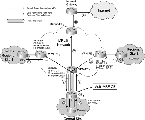
The most common use for Multi-lite VRF is for Internet and VPN services via a single CE, as depicted in Figure 9-11.
Figure 9-11. Application: Internet Services and VPN Services Using a Single CE

We will use this scenario as a case study example in this section. Note that there is no need for policy routing when deploying this example. The premise is that all routes to and from the Internet are directed to the CE, which connects to the firewall at the central site.
Configuration Example for Internet and VPN Service Using the Same CE
A default route is applied in the global table in order to route customer traffic to the firewall. This is then advertised to the VPN, as it was for the policy routing solution.
A static route is applied to the Internet VRF in order to route traffic arriving from the Internet toward the firewall. Another route is also applied to the VRF in order to provide a route back to the Internet. This can be via a default route or a dynamic routing protocol. The advantage of this solution is the ease of using a dynamic routing protocol for the Internet routes. It is possible to use the same routing protocol for both the customer/VPN and Internet routing but still keep them segregated from each other; this is done by using an address family within the routing process so that there is no leaking of routes from one environment to the other.
This solution has the same security limitations as the policy routing solution, although only the addresses within the Internet VRF are reachable directly from the Internet; other addresses on the router are routed via the firewall. If access is gained to the router, it is still possible to hop to the VPN; and if the router is the victim of a denial of service (DoS) attack, the VPN will still be affected.
The solution will work on a wide range of link encapsulation methods, but it will only work on routers supporting VRFs.
Example 9-8 is for CE3 on Figure 9-11. Some of the technology used to separate different customers across the common MPLS core is used to separate the customer and Internet traffic within the CE. The CE is configured with a VPN routing and forwarding (VRF) instance that is applied to the insecure and Internet interfaces. This means that the VPN and customer interfaces are considered to be part of the router's global routing and forwarding tables, but the insecure and Internet interfaces have a different routing and forwarding table.
NOTE
This implementation example is an alternative to policy routing and having separate routers, and in Figure 9-11 we illustrate the data flow from Regional Site 1 to the Internet and the data flow from Regional Site 2 to the Internet. The flow is broken down into steps. CE3 is configured for Multi-VRF/VRF-lite.
Example 9-8. CE3 in Figure 9-11
ip vrf Internet

rd 65000:1

ip cef

!

interface Serial0/0

description *** Serial link to PE ***

 no ip address

 encapsulation frame-relay

!

interface Serial0/0.100 point-to-point

 description *** VPN sub-interface ***

 ip address 192.168.1.1 255.255.255.252

 frame-relay interface-dlci 100

!

interface Serial0/0.200 point-to-point

 description *** Internet sub-interface ***

 ip vrf forwarding Internet

 ip address 172.25.1.1 255.255.255.252

 frame-relay interface-dlci 200

!

interface FastEthernet1/0

 description *** Customer LAN ***

 ip address 10.0.2.1 255.255.255.0

 no ip redirects

!

interface FastEthernet1/1

 description *** Insecure LAN ***

 ip vrf forwarding Internet

 ip address 10.0.1.2 255.255.255.0

 no ip redirects

!

ip route vrf Internet 0.0.0.0 0.0.0.0 Serial0/0.200 172.25.1.2

ip route vrf Internet 10.0.0.0 255.255.0.0 FastEthernet1/0.2 10.0.1.1

router bgp 3

 bgp log-neighbor-changes

 neighbor 192.1.3.1 remote-as 13

 neighbor 192.1.3.1 update-source Ethernet0/1.13

!

ip classless

ip route 220.1.65.16 255.255.255.252 192.1.4.1
One note on Multi-lite VRF scalability factors that are limited by the platform max interfaces: memory for routes and raw processing ability and the actual performance may vary based on traffic load, number of routes, and routing processes.
Multi-VRF/VRF-lite offers the following benefits:
Only one CE router is needed to facilitate provisioning and network management rather than a multiple CE router solution.
A CE router has VRF functionality without full PE functionality to provide BGP routing tables.
It overlaps customer address spaces.
It can coexist with an MPLS-based network with no MPLS enabled on the CE.
NOTE
As we pointed out in Chapter 4, while a shared access line with the CE for Multi-lite VRF facilitates service separation, a DoS attack might affect the VPN on the PE, the single physical link between the PE and the CE, and the CE itself.


