Foundation Topics
Basic Configuration of Integrated IS-IS
Routing always starts with a topology that allows summarization and the selection of addresses that can be summarized. Routing protocols assume that these foundations are in place. When ready, the configuration of Integrated IS-IS is straightforward.
Step 1. | Enable the routing process Integrated IS-IS with the router isis command. |
Step 2. | Configure the Network Entity Title (NET) address, which assigns the area: net network-address. |
Step 3. | Enable IS-IS for IP on the relevant interfaces with the ip router isis interface subcommand. |
Figure 10-1 illustrates a simple network to support the working configuration example. The figure shows the topology and addressing scheme of the network.
Figure 10-1. Basic Integrated IS-IS Configuration
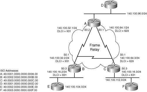
Example 10-1 shows the basic configuration required to run IS-IS. The relevant commands are followed by a brief explanation of the code. Note that the router process is started and the NET address is defined beneath the router process. The ISO address is assigned to the router and is similar to an OSPF router-id, but also implies area assignment. IS-IS is then started on the interfaces.
Example 10-1. Basic Integrated IS-IS Configuration on Router A
|
Code View: interface Ethernet0 ip address 140.100.96.1 255.255.255.0 !assign the IP address and mask ip router isis !start IS-IS on the interface ! interface Serial0 no ip address encapsulation frame-relay ! interface Serial0.1 point-to-point ip address 140.100.64.1 255.255.255.0 !assign the IP address and mask ip router isis !start IS-IS on the interface frame-relay interface-dlci 629 ! interface Serial0.2 point-to-point ip address 140.100.32.1 255.255.255.0 !assign the IP address and mask ip router isis !start IS-IS on the interface frame-relay interface-dlci 931 ! router isis net 49.0001.0000.0000.000a.00 !Start IS-IS and define ISO address. |
Remember that by default, Cisco routers are configured as Level 1-2 routers. Also remember that the clns routing command, which turns on OSI routing, is not required for IP—only IS-IS.
Optional Integrated IS-IS Commands
The commands in this section are optional in the sense that they are not appropriate for all situations. Frame Relay, for instance, requires some IS-IS customization. Another example of an "optional" issue is area assignment and routing level responsibilities.
Changing the Router from Level 1-2
By default, routers support both Level 1 and Level 2 routing. Routing at both levels means twice as many hellos and advertisements, twice as much memory consumed, and twice as much processing. However, routing at both levels makes configuration easier. One easy way to optimize IS-IS is to reduce the unnecessary duplication of routing at both levels.
IS-IS level is set under the IS-IS process using the is-type level-1 or is-type level-2 commands. Once applied, all interfaces communicate only at the given level.
With the topology in Figure 10-2, Routers D, E, and F only need to support Level 1 because they are internal to their areas.
Figure 10-2. Changing Routing Level
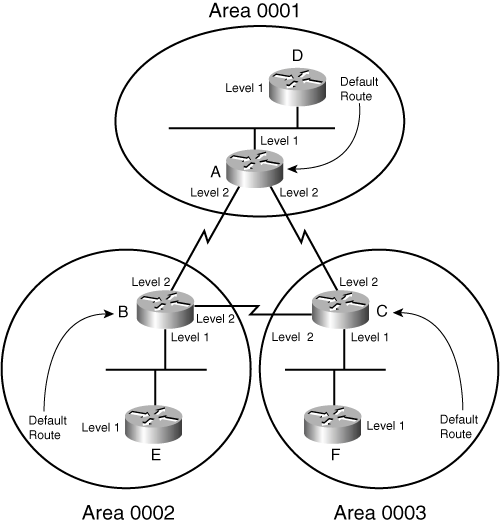
In Example 10-2, Router D is set to route only at Level 1. Note that this command appears under the router isis command, changing the behavior of the entire process.
Example 10-2. Changing the Level of Routing for the Entire Router
interface Ethernet0 ip address 140.100.96.2 255.255.255.0 ip router isis ! router isis net 49.0001.0000.0000.000d.00 is-type level-1 !Define the router as a Level 1 router |
Routing level may also be set per-interface by issuing the isis circuit-type level-1 orisis circuit-type level-2-only commands in interface configuration mode. In Figure 10-2, this is done on Routers A, B, and C. The serial interface should be configured as Level 2 by issuing the isis circuit-type level-2-only command.
Level 1-2 routers send LSPs with an attached (ATT) bit in their Level 1 LSPs. This indicates that they are attached to another area and is interpreted by the receiver as a default route. Thus the Level 2 router serves as a transit router between areas.
In reference to Figure 10-2, Example 10-3 shows Router A configured as Level 1 on the Ethernet interface pointing to Router D. The other interfaces are configured as Level 2 only.
Example 10-3. Changing Router A Routing Level on an Interface Basis
|
Code View: interface Ethernet0 ip address 140.100.96.1 255.255.255.0 ip router isis isis circuit-type level-1 !Configure Level 1 routing on the interface ! interface Serial0 no ip address encapsulation frame-relay ! interface Serial0.1 point-to-point ip address 140.100.64.1 255.255.255.0 ip router isis frame-relay interface-dlci 629 isis circuit-type level-2-only ! Configure Level 2 routing on the interface ! interface Serial0.2 point-to-point ip address 140.100.32.1 255.255.255.0 ip router isis frame-relay interface-dlci 931 isis circuit-type level-2-only !Configure Level 2 routing on the interface ! router isis |
Configuring Summarization
Once the IP addressing scheme is understood, configuring summarization in IS-IS is straightforward. There are three rules to remember about summarizing IP routes with IS-IS:
Summarization is configured on Level 1-2 routers.
All the Level 1-2 routers in the area need to summarize equivalently. If one router is offering more specific routes, all traffic to the area will return via this router in accordance with the longest-match rule.
Routes cannot be summarized within an area, only between areas.
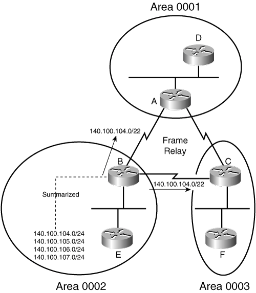
To configure summarization, enter the summary-address command followed by the summary address and mask under the router process. Figure 10-3 shows the topology used to support the working example shown in Example 10-4. In Figure 10-3, the IP routes from Router B are summarized into areas 0001 and 0003. Router B is a Level 1-2 router, straddling more than one area and forming the connectivity between the areas. A Level 1-2 router is similar to an ABR in OSPF. Example 10-4 shows Router B summarizing routes 140.100.104.0 through 140.100.107.0 with a mask summarized from /24 to /22.
Figure 10-3. Summarizing IP Addresses on Router B Between IS-IS Areas
Example 10-4. Summarization of IP Routes from Router B
|
Code View: interface Ethernet0 ip address 140.100.104.1 255.255.255.0 ip router isis isis circuit-type level-1 ! interface Serial0 no ip address encapsulation frame-relay ! interface Serial0.2 point-to-point ip address 140.100.32.2 255.255.255.0 ip router isis isis circuit-type level-2-only frame-relay interface-dlci 931 ! interface Serial0.3 point-to-point ip address 140.100.16.2 255.255.255.0 ip router isis isis circuit-type level-2-only frame-relay interface-dlci 631 ! router isis summary-address 140.100.104.0 255.255.252.0 ! Advertises 140.100.104.0/22 net 49.0002.0000.0000.000b.00 |
Configuring NBMA
IS-IS recognizes two types of network topologies: broadcast and point-to-point. If the network link is not a serial line connecting to a single router (a point-to-point network), IS-IS automatically defines the link as broadcast. Because NBMA is neither a point-to-point nor a broadcast medium, the configuration for IS-IS over NBMA deserves consideration.
For multiaccess WAN interfaces (such as ATM, Frame Relay, and X.25), it is highly recommended that you configure the NBMA cloud as multiple point-to-point subinterfaces. This is a simpler design than trying to use the broadcast mode that makes routing more robust and configuration and support more straightforward.
Frame Relay is an example of an NBMA technology. It supports both point-to-point and meshed environments. The following sections describe both techniques; however, the recommended way to run IS-IS over Frame Relay is to use point-to-point subinterfaces.
Broadcast Configuration over NBMA
If the NBMA cloud is fully meshed, IS-IS broadcast is an option (although it is not recommended). If used, IS-IS treats the cloud as a broadcast medium and elects a DIS. If you manually choose the DIS, you must take into consideration the topology, data flow, and router capacity.
This option is discouraged because of its complexity. The configuration is more involved and the topology is less efficient.
Remember that hello and routing updates are used differently in broadcast environments and point-to-point links. You need to ensure that all the interfaces connecting into the cloud are configured in the same way; otherwise, the hellos will be rejected and no adjacency will form.
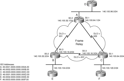
The configuration for IS-IS over a fully meshed Frame Relay cloud is illustrated in Figure 10-4. In the figure, the Frame Relay cloud has three fully meshed routers.
Figure 10-4. NBMA Frame Relay Cloud Running Broadcast Integrated IS-IS
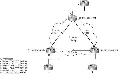
Example 10-5 shows a working example of the configuration shown in the preceding figure. In the example, the frame-relay map ip command maps the IP destination address to the outgoing data-link connection identifier (DLCI) and defines the interface as a broadcast interface. Integrated IS-IS uses the links as if they were a broadcast link and elects a DIS.
The frame-relay map clns command maps a DLCI to the CLNS process on the destination router. Without this command, no routes appear in the IP routing table because IS-IS does not receive IS-IS frames containing LSPs. IS-IS information does not travel in IP or CLNS packets. IS-IS is encapsulated in a frame similar to CLNS and that frame must be received to build a routing table.
Example 10-5. Frame Relay Cloud Running Broadcast Integrated IS-IS
interface Ethernet0
 ip address 140.100.96.1 255.255.255.0
 ip router isis
 isis circuit-type level-1
!
interface Serial0
 ip address 140.100.64.1 255.255.255.0
 ip router isis
 encapsulation frame-relay
 frame-relay map clns 629 broadcast
 !Maps DLCI to the clns process of Router C
 frame-relay map clns 931 broadcast
 !Map DLCI to the clns process of Router B
 frame-relay map ip 140.100.64.2 931 broadcast
 !Maps DLCI to the Destination  IP address of Router B
 frame-relay map ip 140.100.64.3 629 broadcast
 !Maps DLCI to the Destination  IP address of Router C
 isis circuit-type level-2-only
!
router isis
net 49.0001.0000.0000.000a.00 |
The alternative (and superior) solution to a broadcast configuration is to define subinterfaces and to configure each subinterface as point-to-point.
Point-to-Point Configuration over NBMA
The point-to-point configuration requires an IP subnet for every link. This is the recommended way to run IS-IS over NBMA and the only way to do it on anything less than a full mesh.
The configuration is simpler, because the link is point-to-point and there is no need to configure frame-relay map commands.
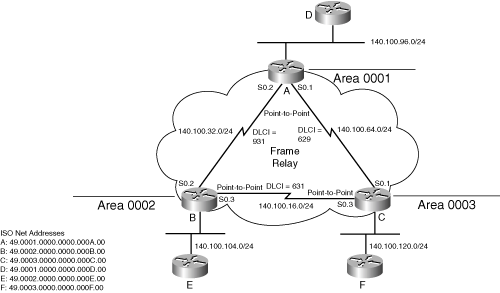
As shown in Example 10-6, it is only necessary to create subinterfaces, configure those interfaces as point-to-point, start Frame Relay, and define the DLCIs. Do not forget that in addition to configuring Frame Relay, you must start the IS-IS process for each interface.
Figure 10-5 supports the working example for this configuration. It shows the DLCI addresses and the IP addresses for the point-to-point links in addition to the ISO addresses for Routers A, B, and C.
Figure 10-5. NBMA Frame Relay Cloud Running Point-to-Point Integrated IS-IS
Example 10-6 shows the configuration for Router A to run IS-IS across Frame Relay as a series of point-to-point networks.
Example 10-6. NBMA Frame Relay Cloud Running Point-to-Point Integrated IS-IS
|
Code View: interface Ethernet0 ip address 140.100.96.1 255.255.255.0 ip router isis ! interface Serial0 no ip address encapsulation frame-relay !Configure Frame Relay for the interface ! interface Serial0.1 point-to-point !Configure subinterface to be point-to-point ip address 140.100.64.1 255.255.255.0 ip router isis frame-relay interface-dlci 629 !Define the DLCI to the destination interface Serial0.2 point-to-point ! Configure subinterface as point-to-point ip address 140.100.32.1 255.255.255.0 ip router isis Frame-relay interface-dlci 931 ! Defines DLCI to the destination ! Router isis net 49.0001.0000.0000.000a.00 |
Verifying the Integrated IS-IS Operation
Useful commands to verify the operation of Integrated IS-IS include the following:
show clns neighbor
show clns interface
show isis database
show isis database detail
The following sections explain each of these show commands in more detail. The commands explained in this section correspond to the topology illustrated in Figure 10-6 and the configuration shown in Example 10-7 for Router A.
Figure 10-6. The Network Topology for the show Commands
Example 10-7. The Configuration for Router A in Figure 10-6
|
Code View: interface Ethernet0 ip address 140.100.96.1 255.255.255.0 ip router isis isis circuit-type level-1 ! interface Serial0 no ip address encapsulation frame-relay ! interface Serial0.1 point-to-point ip address 140.100.64.1 255.255.255.0 ip router isis isis circuit-type level-2-only frame-relay interface-dlci 629 ! interface Serial0.2 point-to-point ip address 140.100.32.1 255.255.255.0 ip router isis isis circuit-type level-2-only frame-relay interface-dlci 931 ! router isis net 49.0001.0000.0000.000a.00 |
The show clns neighbors Command
The show clns neighbors command includes some of the contents of the neighbor table and the state of the link. Note that the subnetwork point of attachment (SNPA) is the MAC address of the interface. Level 1-2 routing is used.
The command has the following syntax:
show clns area-tag neighbors [type number] [area] [detail]
Table 10-2 explains the syntax of this command.
| Field | Description |
|---|---|
| area-tag | Used in multi-process IS-IS configurations, this is a name for a process. |
| type number | (Optional) Type of interface and interface number (for example, Ethernet 1). |
| Area | (Optional) Shows CLNS multiarea adjacencies. |
| detail | (Optional) Shows details of each adjacency. |
Example 10-8 shows output for the show clns neighbors command.
Example 10-8. Output for the show clns neighbors Command
RouterA#show clns neighbors
System Id       Interface  SNPA           State   Holdtime Type Protocol
0000.0000.000B   Se0.2     DLCI 931         Up      22      L2   IS-IS
0000.0000.000C   Se0.1     DLCI 629         Up      23      L2   IS-IS
0000.0000.000D Et0 00e0.1e3d.d56f Up 8 L1 IS-IS |
The output of the show clns neighbors command shows that Router A has three neighbors. The system ID shows that the serial subinterface S0.1 has heard an LSP from 0000.0000.000C, which has a Frame Relay DLCI of 629. It is running IS-IS Level 2 routing. The link is up and has 23 seconds before another Hello needs to be received. Because the Hello timer is set by default to send Hellos every 10 seconds, it should receive another Hello in 7 seconds, which will reset the holdtime. The Ethernet segment is running Level 1 routing and has a MAC address for the SNPA address.
The show clns neighbors command is useful for quickly checking connectivity. This output shows all the neighbors—complete with the DLCI addresses and OSI system IDs—indicating that Frame Relay is correctly configured and working, as is IS-IS.
Adding the parameter detail to the show clns neighbors command gives information about each neighbor. Example 10-9 shows output for the show clns neighbors detail command. The example shows the area address for the neighbor, the IP address of the transmitting interface, and the length of time that the interface has been up. This command gives information that enables you to verify the addressing scheme of the network.
Example 10-9. Output for the show clns neighbors detail Command
RouterA#show clns neighbor detail
System Id         Interface    SNPA           State  Holdtime Type Protocol
0000.0000.000B     Se0.2       DLCI 931          Up     27       L2   IS-IS
 Area Address(es):  49.0002
 IP Address(es):   140.100.32.2*
 Uptime: 00:05:17
0000.0000.000C     Se0.1       DLCI 629          Up     28       L2   IS-IS
 Area Address(es):  49.0003
 IP Address(es):   140.100.64.3*
 Uptime: 00:05:22
0000.0000.000D     Et0         00e0.1e3d.d56f    Up     7        L1   IS-IS
 Area Address(es):  49.0001
 IP Address(es):   140.100.96.2*
Uptime: 00:15:01 |
Table 10-3 explains the meaning of the fields in the detailed output.
| Field | Description |
|---|---|
| System Id | The system address (6 bytes). |
| Interface | Interface on which the neighbor was learned. |
| SNPA | Subnetwork point of attachment (data-link address). |
| State | States are as follows:
|
| Holdtime | Seconds before this adjacency times out. |
| Type | Types of adjacency include
|
| L1 | (Optional) Displays Level 1 adjacencies. |
| L1L2 | (Optional) Shows Level 1 and Level 2 adjacencies. |
| L2 | (Optional) Displays Level 2 adjacencies. |
| Protocol | The routing protocol used to learn the adjacency (ES-IS, IS-IS, ISO IGRP, Static, or DECnet). |
The show clns interface Command
Misconfiguration of the interface can result in the inability to create adjacencies. Typically, the error is a simple mismatch of parameters, which can be seen by using the show clns interface command.
Router#show clns interface [type number]
In Example 10-10, Frame Relay is configured with point-to-point links. The circuit ID shows the system ID of a router, rather than a pseudonode. The octet following the system ID indicates whether this ID is a pseudonode representing the multiaccess link. If the ID is that of a pseudonode, the system ID is that of the DIS, with the next octet showing a nonzero value such as 0x01.
This is confirmed when you look at the Ethernet interface. The Ethernet 0 interface has the Level 1 circuit ID as A.01. This indicates that the DIS for Level 1 is Router A and that A is a pseudonode.
Because this is a Level 1-2 router, there is also a circuit ID for the Level 2 adjacency on the Ethernet interface. Note that the value for the Level 2 DIS is that of Router A. Router D has been configured as a Level 1 router and, as such, cannot communicate Level 2 updates.
Example 10-10 shows output for the show clns interface command.
Example 10-10. Output for the show clns interface Command
|
Code View: RouterA#show clns interface Ethernet0 is up, line protocol is up Checksums enabled, MTU 1497, Encapsulation SAP ERPDUs enabled, min. interval 10 msec. CLNS fast switching enabled CLNS SSE switching disabled DEC compatibility mode OFF for this interface Next ESH/ISH in 47 seconds Routing Protocol: IS-IS Circuit Type: level-1-2 Interface number 0x0, local circuit ID 0x1 Level-1 Metric: 10, Priority: 64, Circuit ID: A.01 Number of active level-1 adjacencies: 0 Level-2 Metric: 10, Priority: 64, Circuit ID A.01 Number of active level-2 adjacencies: 1 Next IS-IS LAN Level-1 Hello in 1 seconds Next IS-IS LAN Level-2 Hello in 1 seconds Serial0 is up, line protocol is up CLNS protocol processing disabled Serial0.1 is up, line protocol is up Checksums enabled, MTU 1500, Encapsulation FRAME-RELAY ERPDUs enabled, min. interval 10 msec. CLNS fast switching disabled CLNS SSE switching disabled DEC compatibility mode OFF for this interface Next ESH/ISH in 58 seconds Routing Protocol: IS-IS Circuit Type: level-1-2 Interface number 0x1, local circuit ID 0x100 Level-1 Metric: 10, Priority: 64, Circuit ID: A.00 Number of active level-1 adjacencies: 0 Level-2 Metric: 10, Priority: 64, Circuit ID: A.00 Number of active level-2 adjacencies: 1 Next IS-IS Hello in 2 seconds Serial0.2 is up, line protocol is up Checksums enabled, MTU 1500, Encapsulation FRAME-RELAY ERPDUs enabled, min. interval 10 msec. CLNS fast switching disabled CLNS SSE switching disabled DEC compatibility mode OFF for this interface Next ESH/ISH in 24 seconds Routing Protocol: IS-IS Circuit Type: level-1-2 Interface number 0x2, local circuit ID 0x101 Level-1 Metric: 10, Priority: 64, Circuit ID: A.00 Number of active level-1 adjacencies: 0 Level-2 Metric: 10, Priority: 64, Circuit ID: A.00 Number of active level-2 adjacencies: 1 Next IS-IS Hello in 886 milliseconds |
Table 10-4 explains the meaning of the fields in the output screen.
| Field | Description |
|---|---|
| Checksum | This may be either enabled or disabled. |
| MTU | Maximum transmission size for a packet on this interface. Note that it is not 1500 because 3 bytes are taken by the OSI header. |
| Encapsulation | The encapsulation is always SAP (ISO1). |
| Routing Protocol | Indicates whether ES-IS or IS-IS is running and the type of Hellos sent. |
| Circuit Type | Indicates whether the link is enabled for Level 1, Level 2, or Level 1-2 routing. |
| Level-1 Metric | Metric value for the outbound interface for Level 1 routing. The default setting is 10. |
| Priority | Priority setting for DIS election. The default is 64. |
| Circuit ID | Identifies the DIS for Level 1 if present. |
| Number of Active Level-1 Adjacencies | The number of Level 1 adjacencies formed on this link. |
| Level-2 Metric | Metric value for the outbound interface for Level 2 routing. The default setting is 10. |
| Priority | The priority setting for DIS election. |
| Circuit ID | Identifies the DIS for Level 2 if present. |
| Number of Active Level-2 Adjacencies | The number of Level 2 adjacencies formed on this link. |
| Next IS-IS LAN Level-1 Hello | Number of seconds before next Hello is expected. Repeat the command to see if Hellos are received. |
| Next IS-IS LAN Level-2 Hello | Number of seconds before next Hello is expected. Repeat the command to see if Hellos are received. |
The show isis database Command
The show isis database command shows the LSPs held in the local database. The LSP ID shows the system ID of the generating router and whether this LSP is from a router or a pseudonode. The last octet shows whether the LSP was too large to fit into one PDU; a nonzero value in this field indicates that this is a fragment of an LSP (the next number states the fragment number).
Because IS-IS is a link-state protocol, the database should be identical on every router of the same level and area.
show isis area-tag database [level-1] [level-2] [l1] [l2] [detail] [lspid]
Table 10-5 explains the syntax.
| Field | Description |
|---|---|
| area-tag | The name for an IS-IS routing process. |
| level-1 | (Optional) Displays the Level 1 link-state database. |
| level-2 | (Optional) Displays the Level 2 link-state database. |
| 11 | (Optional) Abbreviation for Level 1. |
| l2 | (Optional) Abbreviation for Level 2. |
| detail | (Optional) Shows each LSP. |
| lspid | (Optional) Identifier for the link-state PDU. Shows the contents of the specified individual LSP. |
Example 10-11 shows output for the show isis database command.
Example 10-11. Output for the show isis database Command
RouterA#show isis database
IS-IS Level-1 Link State Database:
LSPID                 LSP Seq Num  LSP Checksum  LSP Holdtime     ATT/P/OL
A.00-00             * 0x00000017   0x76D5        876              1/0/0
IS-IS Level-2 Link State Database:
LSPID                 LSP Seq Num  LSP Checksum  LSP Holdtime     ATT/P/OL
A.00-00             * 0x00000018   0xB74F        881              0/0/0
0000.0000.000B.00-00  0x0000001A   0xB561        872              0/0/0
0000.0000.000B.01-00  0x00000016   0x6045        1095             0/0/0
C.00-00               0x0000001E   0x6267        869              0/0/0
C.01-00               0x00000002   0xF25F        958              0/0/0
0000.0000.000E.00-00  0x00000018   0x010A        858              0/0/0
0000.0000.000D.00-00  0x0000001A   0x413C        985              0/0/0
0000.0000.000D.04-00 0x00000017 0xFCA0 1006 0/0/0 |
Table 10-6 explains the meaning of the fields in the output. Note that both Level 1 and Level 2 databases are shown because the router is running the default configuration of Level 1-2 routing. All the LSP information is contained in these databases, including the LSPs generated by the router itself. An asterisk marks these entries in the output.
| Field | Description |
|---|---|
| LSPID | The LSPID indicates the transmitting router. The system ID is followed by two octets. If the first octet has a value greater than 0x00, this indicates that the ID is the DIS. The last octet is the Fragment bit. If the value is 0x00, the entire LSP was carried in one LSP. Otherwise it indicates this PDU is the nth fragment of the LSP. |
| LSP Seq Num | Sequence number for the LSP. This allows routers to determine whether they have received the latest information from the source and ensures the integrity of the link-state database. |
| LSP Checksum | Checksum of the entire LSP packet. |
| LSP Holdtime | Amount of time the LSP remains valid (in seconds). An LSP holdtime of 0 indicates that this LSP was purged and is being removed from the link-state database. |
| ATT | The LSP indicates that this router is a Level 2 router with a path out of the area. Level 1 routers use the presence of this bit to identify the closest Level 1-2 router to send their out-of-area data to. |
| P | Partition repair capability. Not supported by Cisco. |
| OL | The Overload bit indicates that the router has an incomplete database because of memory overload and is therefore not used for transit data. |
The show isis database detail Command
The show isis database detail command shows the complete LSP and the values for the individual fields. The command has the same syntax as the show isis database command in the preceding section.
Example 10-12 shows output for the show isis database detail command. The example shows, for each LSP, the area and the IP address of the transmitting interface and the metric cost to the IP routes it knows. The default metric is a cost of 10; therefore, a metric of 20 indicates a prefix is two hops away.
Example 10-12. Output for the show isis database detail Command
|
Code View: RouterA#show isis database detail
IS-IS Level-1 Link State Database:
LSPID LSP Seq Num LSP Checksum LSP Holdtime ATT/P/OL
A.00-00 * 0x00000017 0x76D5 873 1/0/0
Area Address: 49.0001
NLPID: 0xCC
Hostname:A
IP Address: 140.100.32.1
Metric: 10 IP 140.100.96.0 255.255.255.0
Metric: 10 IP 140.100.64.0 255.255.255.0
Metric: 10 IP 140.100.32.0 255.255.255.0
Metric: 10 IS A.01
IS-IS Level-2 Link State Database:
LSPID LSP Seq Num LSP Checksum LSP Holdtime ATT/P/OL
A.00-00 * 0x00000018 0xB74F 877 0/0/0
Area Address: 49.0001
NLPID: 0xCC
Hostname: A
IP Address: 140.100.32.1
Metric: 10 IS 0000.0000.000B.00
Metric: 10 IS C.00
Metric: 10 IS 0000.0000.000D.04
Metric: 10 IP 140.100.96.0 255.255.255.0
Metric: 10 IP 140.100.64.0 255.255.255.0
Metric: 10 IP 140.100.32.0 255.255.255.0
0000.0000.000B.00-00 0x0000001A 0xB561 868 0/0/0
Area Address: 49.0002
NLPID: 0xCC
IP Address: 140.100.16.2
Metric: 10 IS 0000.0000.000B.01
Metric: 10 IS A.00
Metric: 10 IS C.00
Metric: 10 IP 140.100.104.0 255.255.255.0
Metric: 20 IP 140.100.105.0 255.255.255.0
Metric: 20 IP 140.100.106.0 255.255.255.0
Metric: 20 IP 140.100.107.0 255.255.255.0
Metric: 10 IP 140.100.32.0 255.255.255.0
Metric: 10 IP 140.100.16.0 255.255.255.0
0000.0000.000B.01-00 0x00000016 0x6045 1089 0/0/0
Metric: 0 IS 0000.0000.000B.00
Metric: 0 IS 0000.0000.000E.00
C.00-00 0x0000001E 0x6267 863 0/0/0
Area Address: 49.0003
NLPID: 0xCC
Hostname: C
IP Address: 140.100.100.1
Metric: 10 IS C.02
Metric: 10 IS A.00
Metric: 10 IS 0000.0000.000B.00
Metric: 10 IP 140.100.100.0 255.255.255.0
Metric: 10 IP 140.100.64.0 255.255.255.0
Metric: 10 IP 140.100.16.0 255.255.255.0
C.01-00 0x00000002 0xF25F 951 0/0/0
Metric: 0 IS C.00
0x00000018 0x010A 850 0/0/0
Area Address: 49.0002
0000.0000.000E.00-00 NLPID: 0xCC
IP Address: 140.100.105.1
Metric: 10 IS 0000.0000.000B.01
Metric: 10 IP 140.100.104.0 255.255.255.0
Metric: 10 IP 140.100.105.0 255.255.255.0
Metric: 10 IP 140.100.106.0 255.255.255.0
Metric: 10 IP 140.100.107.0 255.255.255.0
Metric: 20 IP 140.100.32.0 255.255.255.0
Metric: 20 IP 140.100.16.0 255.255.255.0
0000.0000.000D.00-00 0x0000001A 0x413C 976 0/0/0
Area Address: 49.0003
NLPID: 0xCC
IP Address: 140.100.97.1
Metric: 10 IS 0000.0000.000D.04
Metric: 10 IP 140.100.96.0 255.255.255.0
Metric: 10 IP 140.100.97.0 255.255.255.0
Metric: 10 IP 140.100.98.0 255.255.255.0
Metric: 10 IP 140.100.99.0 255.255.255.0
0000.0000.000D.04-00 0x00000017 0xFCA0 996 0/0/0
Metric: 0 IS 0000.0000.000D.00
Metric: 0 IS A.00
|
Table 10-7 explains the meaning of the fields in the output.
| Field | Description |
|---|---|
| Area Address | Area addresses that may be reached from this router. Level 1 LSPs describe the area addresses configured manually on the originating router. Level 2 LSPs describe the area addresses for the area to which this route belongs. |
| Metric | The cost of the outbound interface between the originating router and the advertised neighbor, or the metric of the compound cost between the advertising router and the advertised destination. |
Troubleshooting the Integrated IS-IS Operation
Unfortunately, even after careful planning, configurations can fail to work and the most scrutinized networks can break down. The show commands are essential for hunting down problems. The following commands are useful for troubleshooting Integrated IS-IS:
The show isis spf-log command
The debug commands
The following sections describe these commands in greater detail.
The show isis spf-log Command
The show isis spf-log command explains a great deal about the SPF calculations on the router. It reveals the events that triggered SPF for the last 20 occurrences.
To display how often, and why, the router has run a full SPF calculation, use the show isis spf-log EXEC command.
Example 10-13 shows output for the show isis spf-log command. The example shows that Router A sent an LSP because it had set the ATT bit, and later it generated a new LSP when new adjacencies came online. This output shows the healthy workings of an IS-IS network, but the command is very useful if the network appears unstable, with routes appearing and disappearing.
Example 10-13. Output for the show isis spf-log Command
|
Code View: RouterA#show isis spf-log
Level 1 SPF log
When Duration Nodes Count Last trigger LSP Triggers
04:23:24 0 1 1 A.00-00 TLVCODE
04:08:46 0 1 1 PERIODIC
03:53:46 0 1 1 PERIODIC
03:38:46 0 1 1 PERIODIC
03:23:46 0 1 1 PERIODIC
03:08:46 0 1 1 PERIODIC
02:53:46 0 1 1 PERIODIC
02:38:46 0 1 1 PERIODIC
02:23:46 0 1 1 PERIODIC
02:08:46 0 1 1 PERIODIC
01:53:46 0 1 1 PERIODIC
01:38:46 0 1 1 PERIODIC
01:23:46 0 1 1 PERIODIC
01:08:46 0 1 1 PERIODIC
00:53:46 0 1 1 PERIODIC
00:38:47 0 1 1 PERIODIC
00:23:47 0 1 1 PERIODIC
00:15:14 0 1 2 A.00-00 ATTACHFLAG LSPHEADER
00:08:46 0 1 1 PERIODIC
Level 2 SPF log
When Duration Nodes Count First trigger LSP Triggers
03:53:48 0 1 1 PERIODIC
03:38:48 0 1 1 PERIODIC
03:23:48 0 1 1 PERIODIC
03:08:48 0 1 1 PERIODIC
02:53:48 0 1 1 PERIODIC
02:38:48 0 1 1 PERIODIC
02:23:48 0 1 1 PERIODIC
02:08:48 0 1 1 PERIODIC
01:53:48 0 1 1 PERIODIC
01:38:48 0 1 1 PERIODIC
01:23:48 0 1 1 PERIODIC
01:08:48 0 1 1 PERIODIC
00:53:48 0 1 1 PERIODIC
00:38:48 0 1 1 PERIODIC
00:23:48 0 1 1 PERIODIC
00:15:22 0 3 5 A.00-00 NEWADJ LSPHEADER TLVCONTENT
00:08:48 0 3 1 PERIODIC
00:05:44 4 4 4 A.00-00 NEWADJ TLVCONTENT
00:05:38 4 7 5 0000.0000.000B.00-00 LSPHEADER TLVCONTENT
|
Table 10-8 explains the fields in Example 10-13.
| Field | Description |
|---|---|
| When | The amount of time since a full SPF calculation occurred (hh:mm:ss). The last 19 occurrences are shown. |
| Duration | Milliseconds it took to complete this SPF run (elapsed time as opposed to CPU time). |
| Nodes | Number of routers and pseudonodes (LANs) calculated in the SPF run. |
| Count | Number of events (such as new LSPs) that occurred while the router was waiting before running full SPF. The router waits five seconds after the first triggered LSP to ensure that all the information is received. |
| Last Trigger LSP | Whenever a full SPF calculation is triggered by the arrival of a new LSP, the ID of the LSP is stored. The LSPID can indicate where to start troubleshooting for any routing instability in an area. If multiple LSPs are causing an SPF run, only the LSPID of the last received LSP is remembered. |
| Trigger | A list of all events that triggered a full SPF calculation. |
The debug Commands
The debug command is a helpful troubleshooting tool, but it does have certain disadvantages, of which you must be aware. The debug command is the highest process priority and can steal CPU time from other processes. It is capable of consuming all the resources on the router, thus becoming the problem instead of helping to solve the problem. It is important to turn on debug just for the specific task to be monitored and to turn it off as soon as the data has been gathered. The no form of this command disables debugging output. You should direct the output to a log file, because each character sent to the console creates a processor interrupt.
Table 10-9 lists options available for monitoring IS-IS.
| Command Option | Description |
|---|---|
| debug isis adjacencies-packets | Displays information on all adjacency-related activity, including
|
| debug isis spf-statistics | Displays statistical information about building routes between routers. Using the statistical information provided, one can determine how long it takes to place a Level 1 IS or Level 2 IS on the shortest path tree (SPT) using the IS-IS protocol. |
| debug isis update-packets | Displays SNPs (CSNPs and PSNPs) and LSPs that are detected by the router. |


