Chapter 13: Video Subsystem Overclocking
Chapter 13: Video Subsystem Overclocking
A computer's performance can be increased significantly by overclocking its video subsystem based on the Accelerated Graphics Port (AGP) video adapter. This can be achieved by increasing the bus frequency or by programmatically raising the operating frequency of the video chip, the video memory, or both, using the latest versions of drivers.
Working with the Bus
Contemporary video adapters are connected to other computer subsystems via the AGP bus, through which all data exchange is accomplished. Thus, the performance of modern video adapters directly depends on the AGP bus frequency.
The AGP bus frequency, in turn, depends on the Front Side Bus (FSB) frequency (GTL+/AGTL+, Alpha EV6). Usually, the AGP bus frequency is specified by dividing the FSB frequency. The most common combinations of FSB and AGP frequencies, implemented in motherboards with the Intel 440BX chipset, are listed in Table 13.1.
|
FSB frequency (MHz) |
AGP frequency (MHz) |
|---|---|
|
66 |
66 |
|
75 |
75 |
|
83 |
83 [*] |
|
100 |
66 |
|
103 |
69 |
|
112 |
75 |
|
124 |
83[*] |
|
133 |
89[*] |
|
[*]Unstable operation is probable |
|
The architecture of most motherboards provides tools for correcting AGP and Peripheral Component Interconnect (PCI) bus frequencies, not only by changing the FSB frequency but also by setting the frequency divider values for the processor bus. This is accomplished via parameters in BIOS Setup or jumpers on the motherboard. By changing the bus frequency values, you can select optimal operating modes for the devices controlled by the buses.
|
FSB frequency (MHz) |
Divider |
AGP frequency (MHz) |
|---|---|---|
|
100 |
2/3 |
66 |
|
133 |
1/2 |
66 |
|
166 |
2/5 |
66 |
|
200 |
1/3 |
66 |
Contemporary high-performance video adapters, based on fast components, provide the ability to change the AGP bus frequency within a wide range. However, even they are not always stable at the high frequencies achieved by processor overclocking. (See Table 13.1.)
Increasing the frequency of the AGP bus, to which the video adapter is connected, improves the throughput, which in turn improves the speed of video-data transmission. This improves the performance of the video subsystem in proportion to the growth of its bus frequency. Architectural features and frequency characteristics of electronic components that serve as a basis for modern video adapters also allow the AGP bus frequency to be increased significantly. Some devices created using fast components, manufactured with the most advanced technologies, retain usability at a frequency of 100 MHz. This is more than 50% higher than the standard AGP frequency (typically set to 66 MHz).
However, the potential of this overclocking method is limited. The maximum growth of the AGP bus frequency provided in Table 13.3 are characteristic of rare, high-quality models of video adapters. As a rule, the limits are lower. The growth of frequency and performance of video adapters also is limited by some components, whose characteristics do not allow them to work at higher frequencies. At the same time, the capabilities of other components are not implemented.
|
FSB (MHz) |
Divider |
AGP (MHz) |
AGP 2X (MB/sec) |
AGP 4X (MB/sec) |
AGP 8X (MB/sec) |
|---|---|---|---|---|---|
|
100 |
2/3 |
66 |
533 |
1,067 |
2,133 |
|
110 |
2/3 |
73 |
587 |
1,173 |
2,347 |
|
120 |
2/3 |
80 |
640 |
1,280 |
2,560 |
|
133 |
2/3 |
89 |
711 |
1,422 |
2,844 |
|
140 |
2/3 |
93 |
747 |
1,493 |
2,987 |
|
133 |
1/2 |
66 |
533 |
1,066 |
2,132 |
|
140 |
1/2 |
70 |
560 |
1,120 |
2,240 |
|
150 |
1/2 |
75 |
600 |
1,200 |
2,400 |
|
160 |
1/2 |
80 |
640 |
1,280 |
2,560 |
|
170 |
1/2 |
85 |
680 |
1,360 |
2,720 |
|
180 |
1/2 |
90 |
720 |
1,440 |
2,880 |
|
166 |
2/5 |
66 |
533 |
1,067 |
2,133 |
|
170 |
2/5 |
68 |
544 |
1,088 |
2,176 |
|
180 |
2/5 |
72 |
576 |
1,152 |
2,304 |
|
190 |
2/5 |
76 |
608 |
1,216 |
2,432 |
|
200 |
2/5 |
80 |
640 |
1,280 |
2,560 |
|
210 |
2/5 |
84 |
672 |
1,344 |
2,688 |
|
220 |
2/5 |
88 |
704 |
1,408 |
2,816 |
|
240 |
2/5 |
96 |
768 |
1,536 |
3,072 |
|
200 |
1/3 |
66 |
533 |
1,067 |
2,133 |
|
210 |
1/3 |
70 |
560 |
1,120 |
2,240 |
|
220 |
1/3 |
73 |
587 |
1,173 |
2,347 |
|
230 |
1/3 |
77 |
613 |
1,227 |
2,453 |
|
240 |
1/3 |
80 |
640 |
1,280 |
2,560 |
|
250 |
1/3 |
83 |
667 |
1,333 |
2,667 |
This statement can be illustrated by an example that overclocked the Matrox Millenium G200 video adapter. This overclocking was accomplished using the standard, built-in tools of the motherboard.
Configuration of the Test System
-
Test — 3D WinBench 98 (800 × 600 × 32)
-
Overclocking parameters — Increase the bus frequency 75/83/103 MHz
-
Video adapter — Matrox Millennium G200, AGP, 250 MHz RAMDAC, 8 MB SGRAM, 128 MB graphics aperture
-
Motherboard — Asus P2B-S
-
Processor — Intel Celeron 300A
-
RAM —128 MB CAS2 SDRAM
-
BIOS — Award Modular BIOS v4.51PG
-
Operating system — Windows 98
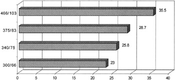
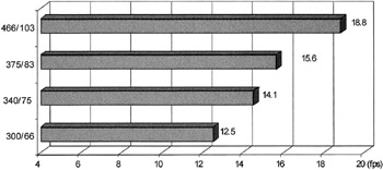
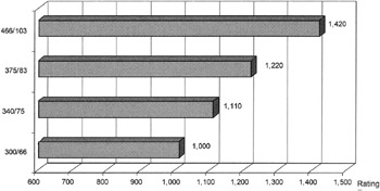
Overclocking of the hardware components was accomplished by increasing the FSB frequency from 66 MHz (the nominal value) to 103 MHz. The growth of video subsystem performance achieved as a result of this overclocking is presented in Table 13.4 and Figs. 13.1–13.3.
|
3D WinBench 98 Test |
300/66 |
340/75 |
375/83 |
466/103 |
|---|---|---|---|---|
|
3D processing |
23.0 |
25.8 |
28.7 |
35.5 |
|
3D scene/user defined (frames per second) |
12.5 |
14.1 |
15.6 |
18.8 |
|
3D WinMark rating |
1,000 |
1,110 |
1,220 |
1,420 |

Figure 13.1: Results of the 3D WinBench 98 (3D processing) test

Figure 13.2: Results of the 3D WinBench 98 (3D scene) test

Figure 13.3: Results of the WinBench 98 (3D WinMark) test


