IEEE 802.1X
IEEE 802.1X is very simple in concept. Its purpose is to implement access control at the point at which a user joins the network. It divides the network universe into three entities along the lines we discussed in the previous section:
Supplicant, which wants to join the network
Authenticator, which controls access
Authentication server, which makes authorization decisions
The point at which a user connects to the network is called a port. A network may have many ports; for example, in a switched LAN hub,[2] each Ethernet connector would be one port. There is a one-to-one relationship between a supplicant and a port, and each port has an associated authenticator to control its state. There is a many-to-one relationship between the ports and the authentication server. In other words, a single authentication server is usually responsible for many ports, each with its own controlling authenticator.
[2] Because each port must act independently, IEEE 802.1X can only be supported by a LAN switch, not a conventional shared LAN hub.
Although wireless is our primary concern, IEEE 802.1X was not originally designed with wireless communication in mind. In fact, work was started on IEEE 802.1X before the first version of IEEE 802.11 was completed in 1997. The opening paragraph of IEEE 802.1X says:
IEEE 802 Local Area Networks are often deployed in environments that permit unauthorized devices to be physically attached to the LAN infrastructure.
Note that the word "physically" implies a wired connection. The original thinking behind IEEE 802.1X was to protect ports such as might be found on a switched Ethernet hub. The idea was to prevent just anyone from connecting to the network by plugging an Ethernet cable into a hole in the wall and, instead, require that a potential user's identity and authorization status be checked. As IEEE 802.1X moved toward completion, people recognized that the same principle could be extended from wired ports to wireless connections. Cisco incorporated the concept into its products first, and the approach was adopted for RSN in IEEE 802.11i and, subsequently, by the Wi-Fi Alliance for WPA.
The main point of providing port security is to protect network connections where those connections might be accessible in a nonsecure area, such as a lobby or conference room. For most corporations this is a small number of ports. But for wireless, it is potentially every connection, because the nature of wireless makes almost all links publicly accessible. This is why IEEE 802.1X is so appropriate for IEEE 802.11.
IEEE 802.1X in a Simple Switched Hub Environment
Before looking at its application in WPA/RSN, let's get an overview of what IEEE 802.1X does in a simple switched hub environment. Control is based around the concept of a switch on each port that is normally open (no connection). The switch is closed only when the supplicant is authorized. As shown in Figure 8.2, the hub ports are all disconnected initially. If anyone plugs in, he doesn't automatically get network access. It is important to note that it would be most unusual for the switches to be implemented as actual physical contacts. The switch here is only logical, like software or logic gates. When the switch is "open," data packets are not forwarded to or from the port. When it is closed, they are sent. The Ethernet port remains electrically active all the time.
Figure 8.2. Initial State of IEEE 802.1X Switched LAN Hub
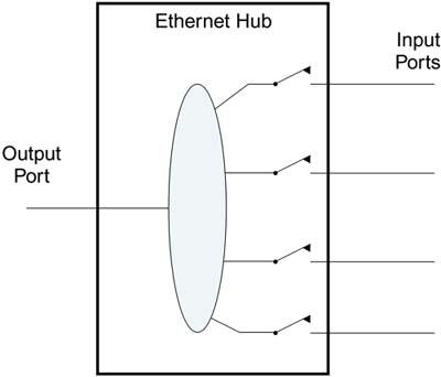
One of the obvious problems in the diagram shown in Figure 8.2 is that it doesn't provide any way for the devices to ask the switched hub for permission to connect. It's like forgetting to put a doorbell on your front door. No one can ring to ask to come in. Remember that each port has an authenticator that is responsible for opening and closing the switch, so IEEE 802.1X provides a way to talk to the authenticator even when the switch is open.
This is like the security guard at the front door of an office building. When you arrive you are not allowed in, but you are allowed to talk to the security guard to ask for entry. In the terminology of IEEE 802.1X, the authenticator has control over the port state (whether the switch is open or closed), as shown in Figure 8.3. Here we see that the device on port 0 has been accepted and is connected to the network; another device is in the process of requesting access to the authenticator on port 1 but does not have access yet. The protocol used to communicate between the supplicant and the authenticator is based on EAP.
Figure 8.3. Role of IEEE 802.1X Authenticator
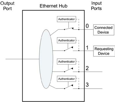
In Figure 8.3, it looks as if the authenticators are making the decisions about who is allowed access. In reality, the decision to admit or reject an applicant is usually based on an authentication database controlled and managed by an administrator. For this, the authenticator must communicate to an authentication server in order to get the answer "accept" or "reject" when a supplicant applies to join the network.
The authenticators in Figure 8.3 act like a security guard that has no authority. For every person who comes to the door, the guard has to call upstairs to the boss to find out whether it is OK to allow access. In a small system, the authentication server (the boss) could reside right in the switched hub and would simply have a list of users allowed access. Typically, the list of users would be configured by the system administrator in advance. This approach is impractical except for the smallest networks because each hub would have to be configured separately. Therefore, the authentication server is typically located at some central place in the network, as shown in Figure 8.4.
Figure 8.4. Role of Remote Authentication Server
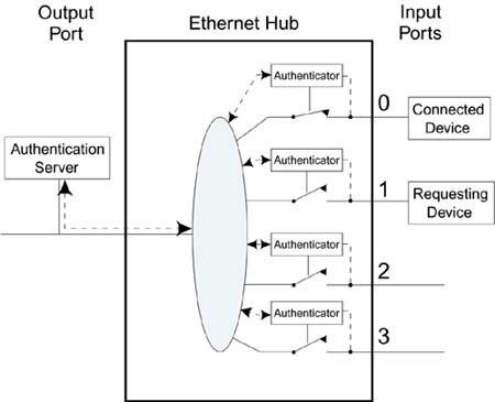
In Figure 8.4, all four authenticators for the hub shown communicate with the authentication server. In practice, the same would be true for all hubs on the network so the authentication server could be making decisions for many thousands of ports (hopefully not at the same time).
Although we have used a picture of a multiport switched LAN hub in these examples, the IEEE 802.1X standard is really only concerned with one port at a time. Each port has its own state independent of any others in the box. Figure 8.5 shows a picture extracted directly from the IEEE 802.1X specification illustrating the relationships among the entities.
Figure 8.5. IEEE 802.1X Model As Shown in IEEE Standard
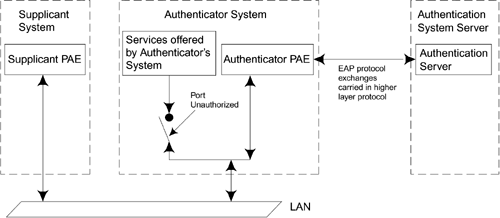
Figure 8.5 again shows the three players: supplicant system, authenticator system, and authentication server system. The supplicant is the device that wishes to get connected. Note that the switch connects through to "services offered by the authenticator's system." Usually we assume this means "connected to the network," but it could be some other service. PAE means port access entity, the full name for a port.
Figure 8.5 includes a reference to a higher-layer protocol between the authenticator and the authentication server. The EAP protocol is used by the various parties to communicate with each other. EAP messages go between the supplicant and the authenticator. The authenticator may also forward them to the authentication server as part of the process of authorization in a similar way that the NAS does in a dial-in network. If the authentication server is in a remote location, these messages need to be sent over a network using some higher-layer protocol. This is where RADIUS can be called into action to transfer the requests over an IP network. RADIUS was designed to perform this job in the dial-up user case, and now we can reuse it for IEEE 802.1X support. WPA specifies RADIUS for this purpose, although other protocols are also possible.
One of the differences between dial-in networks and IEEE 802.1X is that, with IEEE 802.1X, there is no need to use PPP because IEEE 802 LANs are designed to send data packets. However, it is still necessary to have some sort of protocol so the receiver can identify the information, and that protocol is called EAPOL (EAP over LAN). As described later in this chapter, EAPOL has several types of messages. Apart from the one that delivers the EAP messages, there are several additional ones that are useful for actions like attracting the attention of the authenticator (the doorbell analogy). Also there is a message for transferring key-related information.[3] WPA and RSN use a similar message in the process of establishing an encrypted link (see Chapter 10).
[3] This message has no use on wired 802 LANs because they do not support cipher suites.
IEEE 802.1X in Wi-Fi LANs
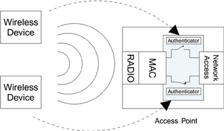
Given that IEEE 802.1X is designed to control individual LAN ports, how does it map to the wireless case in which there is a single access point supporting many devices? We have to treat each wireless connection between a mobile device and the access point as if it were an independent connection. In effect, we replace the physical connections of a switched LAN hub with logical connections formed by the wireless communications.
In the context of IEEE 802.1X, each mobile device is a supplicant wanting to be provided with the services of the access point (which typically means connection to a wired network). To accomplish this, the access point must create, for each supplicant it encounters, a logical port complete with an authenticator. Each authenticator is responsible for controlling access for the mobile supplicant to which it has been assigned. Along with the logical port and authenticator, there is also a logical control switch. As you would expect, the control switch starts in the open position.
A new wireless device, acting as a supplicant, has to apply for access by sending messages to the authenticator, which controls its connection inside the access point. All this is done in software. There is no physical authenticator or switch, so the number of IEEE 802.1X entities in operation is the same as the number of associated mobile devices, regardless of how many that might be (Figure 8.6).
Figure 8.6. Logical IEEE 802.1X Ports in an Access Point
It is a common misconception that IEEE 802.1X is only relevant to big corporate environments in which there are dedicated authentication servers. However, in practice, the authentication server could be a simple process inside the access point?just a list of user names and passwords, for example. This means that the same principles of IEEE 802.1X that apply for huge networks can also apply to home networks. If the authentication server is built inside the access point, there is no need to use RADIUS because the authenticator and authentication server do not need to talk over the network; they are in the same box! However, in this case the number of supported authentication methods would be limited to those selected by the equipment vendor.
So far we have mostly talked about IEEE 802.1X in the context of access control. This has been described as a sort of one-time operation: The supplicant requests access and the authenticator grants it after referring to the authentication server. This may be sufficient for dial-up access or for Ethernet LAN ports because there is a physical connection for each supplicant and it is very hard for an attacker to take over that connection once it is authorized. Clearly the same is not true for Wi-Fi LANs. Without protection, it would be trivially easy for an attacker to wait until a valid user was granted access and then start using the connection by stealing his identity. Therefore, for Wi-Fi LANs, we have to bind the authorization to a mechanism that prevents this type of session hijack. This is accomplished by incorporating message authentication (integrity) as part of the authorization process. We must be sure that both the access point and the mobile device have their secret keys in place by checking message authenticity and that they have turned on encryption before granting access to the network. This important difference greatly complicates the process and resulted in some minor changes to IEEE 802.1X to ensure synchronization of the process. A new standard, IEEE 802.1AA, is being developed at the time of writing to update IEEE 802.1X partly as a result of its application to IEEE 802.11i. To explore the way that synchronization is achieved, see Chapter 10.


