13.2 Serial ATA
The Serial ATA Working Group (http://www.serialata.org) is a group of companies led by APT, Dell, Intel, Maxtor, and Seagate. In August 2001, this group released the Serial ATA Specification 1.0, which defines a replacement for the parallel ATA physical storage interface.
Serial ATA (SATA) drives and interfaces were originally expected to ship in volume in late 2001, but various technical and marketing reasons delayed deployment by a year or more. By late 2002, SATA motherboards and drives were in limited distribution. Maxtor and Western Digital had planned to ship SATA drives in 2002, but failed to do so, leaving Seagate as the only hard drive maker shipping SATA drives in significant quantities through early 2003.
Motherboards also lacked native SATA support until spring 2003. Beginning in fall 2002, a few premium motherboards such as the Intel D845PEBT2 and the ASUS A7N8X Deluxe incorporated SATA support, but those transition motherboards merely grafted on SATA support using third-party support chips. Native chipset-level SATA support had to wait for the arrival in spring 2003 of motherboards based on Intel Springdale- and Canterwood-series chipsets.
Despite the slow start, SATA is on track to replace PATA, particularly for hard drives. By late 2003, most mainstream hard drives and motherboards will be native SATA products. Although SATA will rapidly become the standard for hard drives, most new motherboards will also have PATA interfaces well into 2005. This is true because manufacturers of ATAPI devices, such as optical drives, will be slower to convert to SATA. PATA is good enough for ATAPI devices, and we suspect ATAPI device makers are concerned about complicating manufacturing, inventory, and distribution by producing both PATA and SATA models.
|
SATA can be used to connect internal storage devices such as hard drives, optical drives, and tape drives to the PC motherboard. Serial ATA 1.0, called Ultra SATA/1500 or SATA/150, operates at 1.5 Gb/s, and provides 150 MB/s read/write performance for storage peripherals. Serial ATA II (Ultra SATA/3000 or SATA/300) is already in the works, and will operate at 3.0 Gb/s. Serial ATA III (Ultra SATA/4500 or SATA/450) is planned, and will operate at 4.5 Gb/s. Table 13-6 compares features of PATA, SATA, and other current high-speed bus standards.
|
Interface |
PATA |
SATA |
SCSI |
USB 2.0 |
IEEE-1394 |
|---|---|---|---|---|---|
|
Internal/External |
|
|
|
-- /
|
|
|
Storage / I/O peripherals |
|
|
|
|
|
|
2001 Speed (MB/s) |
100 |
n/a |
160 |
1.5 |
50 |
|
2002 Speed (MB/s) |
100/133 |
150 |
160 |
60 |
50 |
|
2003 Speed (MB/s) |
133 |
150 |
160/320 |
60 |
100 |
|
2004 Speed (MB/s) |
133 |
300 |
320 |
60 |
200 |
|
Cable length (m) |
0.45 |
1.0 |
12.0 |
5.0 |
4.5 |
|
Bootable? |
Yes |
Yes |
Yes |
No |
No |
|
Embedded interface? |
Yes |
Yes |
Seldom |
Yes |
Seldom |
|
Hot-pluggable? |
No |
Yes |
Yes |
Yes |
Yes |
SATA II is more than just a faster version of SATA 1.0. SATA II is to be introduced in two phases.
Phase 1 interfaces and drives, which we expect to ship in late 2003 or early 4003, target the small server and network storage markets. Phase 1 maintains the 150 MB/s data rate of SATA 1.0, but adds SCSI-like features such as command queuing, data scatter/gathering, and out-of-order execution and delivery. Phase I enhances manageability with features such as fan control, activity indicators, temperature control, and new device notification, and extends cabling lengths to allow rack-mounted hot-swappable arrays. Using these new features requires updated drivers and OS support (versus SATA 1.0, which is fully compatible with standard ATA drivers), but SATA II interfaces will be compatible with SATA 1.0 drives.
Phase 2 interfaces and drives, which we expect to ship during 2004, target the midrange server and network storage markets. Phase 2 increases the data rate to the second-generation 300 MB/s and includes various physical and topological improvements intended to support larger arrays of drives. As with Phase 1, Phase 2 requires updated drivers and OS support, but maintains backward compatibility with SATA 1.0 drives.
We don't expect to see SATA III products until at least 2005, so we'll reserve comment on them until we know a bit more about them.
13.2.1 SATA Features
SATA has the following important features:
- Reduced voltage
-
Current ATA standards use 5.0V or 3.3V (ATA-100/133). These relatively high voltages in conjunction with high pin densities make 100 MB/s the highest data rate that is realistically achievable. SATA uses 500 millivolt (0.5V) peak-to-peak signaling, which results in much lower interference and crosstalk between conductors.
- Simplified cabling and connectors
-
SATA replaces the 40-pin/80-wire parallel ATA ribbon cable with a seven-wire cable. In addition to reducing costs and increasing reliability, the smaller SATA cable eases cable routing and improves airflow and cooling. An SATA cable may be as long as 1 meter (39+ inches), versus the 0.45-meter (18 inch) limitation of standard ATA. This increased length contributes to improved ease of use and flexibility when installing drives, particularly in tower systems. The smaller and less-expensive SATA connector replaces the large, cumbersome 40-pin connectors used by standard ATA.
- Differential signaling
-
In addition to three ground wires, the seven-wire SATA cable uses a differential transmit pair (TX+ and TX-) and a differential receive pair (RX+ and RX-).
- Improved data robustness
-
In addition to using differential signaling, SATA incorporates superior error detection and correction, which ensures the end-to-end integrity of command and data transfers at speeds greatly exceeding those available with standard ATA.
- Operating system compatibility
-
SATA appears identical to PATA from the viewpoint of the operating system. This means that current operating systems can recognize and use SATA interfaces and devices using existing drivers.
- Point-to-point topology
-
Unlike PATA, which permits connecting two devices to a single interface, SATA dedicates an interface to each device. This helps performance in three ways. First, each SATA device has a full 150 MB/s of bandwidth available to it. Although current drives are not bandwidth-constrained by PATA interfaces, as faster drives become available this will become an issue. Second, PATA allows only one device to use the channel at a time, which means a device may have to wait its turn before writing or reading data on a PATA channel. SATA devices can write or read at any time, without consideration for other devices. Third, if two devices are installed on a PATA channel, that channel always operates at the speed of the slower device. For example, installing a UDMA-6 hard drive and a UDMA-2 optical drive on the same channel means the hard drive must operate at UDMA-2. SATA devices always communicate at the highest data rate supported by the device and interface.
- Forward and backward device compatibility
-
SATA backers appreciate that there will be a transition period during which PATA and SATA must coexist. Inexpensive dongles will adapt PATA devices to SATA interfaces, and SATA devices to PATA interfaces.
|
13.2.2 SATA Connectors and Cables
SATA uses simplified connectors and cables. Connectors are keyed unambiguously. The 15-pin SATA Power Connector, shown in Table 13-7, and the seven-pin SATA Signal Connector, shown in Table 13-8, each use a single row of pins with 0.050 inch (1.27mm) spacing. SATA makes provision for hot-plugging using blind backplane connectors. The mating sequence for such connectors is shown in Table 13-7 and Table 13-8 in the Mating column. Connections for ground pins P4 and P12 are made first, connections for the precharge power pins and the remaining ground pins are made second, and connections for the signal pins and remaining power pins are made third.
|
Pin |
Signal |
Usage |
Mating |
|---|---|---|---|
|
P1 |
V33 |
3.3 V power |
Third |
|
P2 |
V33 |
3.3 V power |
Third |
|
P3 |
V33 |
3.3 V power, precharge |
Second |
|
P4 |
Gnd |
Ground |
First |
|
P5 |
Gnd |
Ground |
Second |
|
P6 |
Gnd |
Ground |
Second |
|
P7 |
V5 |
5 V power, precharge |
Second |
|
P8 |
V5 |
5 V power |
Third |
|
P9 |
V5 |
5 V power |
Third |
|
P10 |
Gnd |
Ground |
Second |
|
P11 |
Reserved | ||
|
P12 |
Gnd |
Ground |
First |
|
P13 |
V12 |
12 V power, precharge |
Second |
|
P14 |
V12 |
12 V power |
Third |
|
P15 |
V12 |
12 V power |
Third |
|
Pin |
Signal |
Usage |
Mating |
|---|---|---|---|
|
S1 |
Gnd |
Ground |
Second |
|
S2 |
A+ |
Differential signal pair A, positive |
Third |
|
S3 |
A- |
Differential signal pair A, negative |
Third |
|
S4 |
Gnd |
Ground |
Second |
|
S5 |
B- |
Differential signal pair B, negative |
Third |
|
S6 |
B+ |
Differential signal pair B, positive |
Third |
|
S7 |
Gnd |
Ground |
Second |
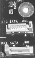
The two ends of an SATA signal cable assembly use identical receptacles. Either cable receptacle can mate to the signal segment of the device plug connector or to the host plug connector. The SATA specification defines the allowable length of an SATA signal cable as to 1 meter. As intriguing as it is to ponder the implications of a 0-meter cable, the real meaning of that part of the specification is that an SATA device can legally be connected directly to the host signal connector, without using a cable. Figure 13-3 shows two SATA signal connectors, with a motherboard mounting hole shown at the upper right for comparison. Note the seven contacts on the connector and the unambiguous keying. The 15-pin SATA power connector uses a similar physical connector, also with unambiguous keying.
Figure 13-3. SATA interface ports

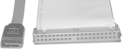
In addition to superior electrical characteristics and greater allowable length, one major advantage of SATA cabling is its smaller physical size, which contributes to neater cable runs and much improved airflow and cooling. Figure 13-4 shows an SATA signal cable on the left and a UDMA ATA cable on the right. Even allowing for the fact that an ATA cable supports two devices, it's clear that using SATA conserves motherboard real estate and greatly reduces cable clutter inside the case.
Figure 13-4. SATA cable (left) and UDMA 80-wire ATA cable

13.2.3 Configuring SATA devices
There's simply not much to say about configuring SATA devices. Unlike with PATA, with SATA you needn't set jumpers for Master or Slave (although SATA does support Master/Slave emulation). Each SATA device connects to a dedicated signal connector, and the signal and power cables are completely standard. Nor do you have to worry about configuring DMA, deciding which devices should share a channel, and so on. There are no concerns about capacity limits because all SATA devices and interfaces support 48-bit LBA. The BIOS, operating system, and drivers all recognize an SATA drive as just another ATA drive, so there's no configuration needed. You simply connect the signal cable to the drive and interface, connect the power cable to the drive, and start using the drive. Everything should be that simple.


