26.3 Power Connectors
All power supplies provide two types of power connectors. The first powers the motherboard and differs according to form factor. The second powers drives and other internal peripherals, and comes in two varieties, which are described in the following sections. Tower/AT and Tower/BAT power supplies include a third type of power connector?a high-voltage cable that connects the power supply to an external main power switch.
26.3.1 AT Main Power Connector
Table 26-11 lists the standard AT Main Power Connector pinouts used by all AT power supply variants, including Desktop/AT, Tower/AT, Desktop/BAT, Tower/BAT, and LPX. PC/XT power supplies use the same pinouts, except that Pin P8-2 is unused. In addition to supplying various standard voltages, this connector includes a special-purpose pin. Pin P8-1, PG, carries the Power Good signal, which the power supply asserts once it has started and stabilized. The motherboard will not attempt to boot until the power supply asserts PG.
|
Pin |
Color |
Signal |
Pin |
Color |
Signal | |
|---|---|---|---|---|---|---|
|
P8-1 |
orange (white) |
PG |
P9-1 |
black |
ground | |
|
P8-2 |
red |
+5V |
P9-2 |
black |
ground | |
|
P8-3 |
yellow |
+12V |
P9-3 |
white (blue) |
-5V | |
|
P8-4 |
blue (brown) |
-12V |
P9-4 |
red |
+5V | |
|
P8-5 |
black |
ground |
P9-5 |
red |
+5V | |
|
P8-6 |
black |
ground |
P9-6 |
red |
+5V |
Note that P8 and P9 are separate connectors from the power supply, but mate to a combined connector on the motherboard.
|
P8 and P9 were IBM's original designation for these connectors. Not all power supplies or motherboards label these connectors, so you may have to determine which is P8 and which is P9 by examining wire colors. The colors shown are those most commonly used, but some AT power supplies use the alternative (ATX) color coding shown in parentheses. We have also seen AT power supplies that use completely nonstandard wire colors, such as green for ground wires.
When installing an AT power supply, the key factor is to ensure that, regardless of wire colors or connector labels, the connectors are aligned so as to place all four ground pins contiguously. It's safer still to examine the documents for the motherboard and power supply. We have seen a few proprietary motherboards and power supplies that used standard connectors but with completely nonstandard pinouts. This was clearly done to force customers to purchase replacement components from the original vendor, and is happily not something you're likely to encounter on any recent system.
26.3.2 ATX Main Power Connector
Table 26-12 lists the pinouts for the ATX Main Power Connector of an ATX or ATX12V power supply. This is a 2X10 connector with Pin 1 keyed. The motherboard connector is a Molex 39-29-9202 or equivalent. The power supply connector is a Molex 39-01-2200 or equivalent. All wires are 18 AWG, except Pin 11, which is specified as 22 AWG. For power supplies 300W or larger, the specification recommends using 16 AWG wires for +3.3VDC, +5VDC, and COM (ground). Note that wire colors are those recommended and commonly used, but may vary.
|
Pin |
Color |
Signal |
Pin |
Color |
Signal | |
|---|---|---|---|---|---|---|
|
1 |
orange |
+3.3VDC |
11 |
orange |
3.3VDC | |
|
2 |
orange |
+3.3VDC |
12 |
blue |
-12VDC | |
|
3 |
black |
COM |
13 |
black |
COM | |
|
4 |
red |
+5VDC |
14 |
green |
PS-- ON | |
|
5 |
black |
COM |
15 |
black |
COM | |
|
6 |
red |
+5VDC |
16 |
black |
COM | |
|
7 |
black |
COM |
17 |
black |
COM | |
|
8 |
gray |
PW-- OK |
18 |
white |
-5VDC | |
|
9 |
purple |
5VSB |
19 |
red |
5VDC | |
|
10 |
yellow |
+12VDC |
20 |
red |
5VDC |
In addition to supplying various standard voltages, this connector includes four special-purpose pins:
- Pin 8 (PW_OK)
-
PW_OK is the ATX equivalent of the AT Power Good signal, which the power supply asserts once it has stabilized. The motherboard will not attempt to boot until the power supply asserts PW_OK.
- Pin 9 (5Vsb)
-
5Vsb is the +5V standby circuit, which supplies +5V at low amperage to the motherboard even when the power supply is off. Any ATX power supply must provide at least 10 mA 5VSB, but motherboards with the Wake-on-LAN (WOL) feature require 720 mA, which all ATX 2.1-compliant power supplies and most good ATX power supplies of earlier vintage also provide.
- Pin 11 (Remote Sensing)
-
On the critical +3.3V rail, small loads can cause large percentage shifts in voltage. This pin provides a means for the power supply to detect the actual voltage present on the +3.3V rail at the main power connector and modify its output to compensate for up to 100 mV of drop due to cable, connectors, and PCB traces, thereby maintaining +3.3V within tolerance.
- Pin 14 (PS_ON)
-
PS_ON is used by the motherboard to turn the power supply on and off.
|
26.3.3 ATX/ATX12V Auxiliary Power Connector
The ATX/ATX12V Auxiliary Power Connector, shown in Table 26-13, is recommended for configurations that require more than 18A of +3.3VDC or more than 24A of +5VDC. This is an inline 6-pin connector with Pin 6 keyed. The motherboard connector is a Molex inline 6-pin 15-48-0412 header or equivalent. The power supply connector is a Molex 90331-0010 or equivalent. All wires are 16 AWG. Wire colors are standard. Few inexpensive power supplies provide this connector, but it is present on some better power supplies. With the shift to ATX12V and 12V VRMs, the importance of this connector is decreasing. Few motherboards include this connector.
|
Pin |
Color |
Signal |
Pin |
Color |
Signal | |
|---|---|---|---|---|---|---|
|
1 |
black |
COM |
4 |
orange |
3.3V | |
|
2 |
black |
COM |
5 |
orange |
3.3V | |
|
3 |
black |
COM |
6 |
red |
5V |
26.3.4 ATX Optional Power Supply Connector
In addition to the main and auxiliary power connectors, ATX 2.1 defines the ATX Optional Power Supply Connector, shown in Table 26-14. This connector is not required for ATX compliance, but provides various benefits, including fan monitoring and control, a remote 3.3V sense line (used to monitor and correct output on the 3.3VDC line), and a power source for IEEE-1394 (FireWire) devices. This is a 2X3 connector with Pin 1 keyed. The motherboard connector is a Molex 39-30-1060 or equivalent. The power supply connector is a Molex 39-01-2060 or equivalent. All wires are 22 AWG. Wire colors are standard. The first color indicates the base color, and the second the stripe color.
|
Pin |
Color |
Signal |
Pin |
Color |
Signal | |
|---|---|---|---|---|---|---|
|
1 |
white |
FanM |
4 |
white/black |
1394R | |
|
2 |
white/blue |
FanC |
5 |
white/red |
1394V | |
|
3 |
white/brown |
Sense |
6 |
NC |
Reserved |
ATX Optional Power Supply Connector signals perform the following functions:
- FanM
-
FanM is a 2-pulse/revolution signal generated by the power supply fan that notifies the system of current fan speed. If this signal drops, the motherboard realizes immediately that the power supply fan has failed, and can shut down the system in an orderly manner.
- FanC
-
FanC is an optional signal generated by some motherboards to control fan speed for power supplies that are designed to allow this. The signal can range from 0VDC to +12VDC. A signal of +1V or less is recognized by the fan as an order to shut down, and a signal of +10.5V or more is recognized as an order to run at full speed. Intermediate voltage levels, which are supported by some motherboards and some fans, allow the system to instruct the fan to run at some intermediate speed. If this signal is left open (0VDC), properly designed fans run at full speed.
- Sense
-
This is a supplementary +3.3VDC remote sense line, which allows the power supply to monitor the actual voltage at the motherboard connector of the nominal +3.3VDC rail and adjust it to stay within specifications.
- 1394R
-
1394R provides an isolated ground return path for the 1394V voltage rail, described next.
- 1394V
-
1394V is a segregated voltage supply rail for powering IEEE-1394 devices. The voltage on this rail depends on the IEEE-1394 implementation, may range between +8VDC and +40VDC, and is typically unregulated. If implemented, this rail should deliver voltage only while PS_ON on the main connector is asserted low.
26.3.5 ATX12V Power Supply Connector
With the introduction of the Pentium 4 processor, Intel extended the ATX 2.03 specification to define a new type of power supply called ATX12V, which is a superset of ATX 2.03, and is now incorporated in the ATX Specification 2.1 and the ATX/ATX12V Power Supply Design Guide Version 1.2. ATX12V power supplies include an additional 2X2 4-pin +12V power connector, shown in Table 26-15. The motherboard connector is a Molex 39-29-9042 or equivalent. The power supply connector is a Molex 39-01-2040 or equivalent. All wires are 20 AWG. Wire colors are standard. The purpose of this new connector is to deliver more +12V current to the motherboard than is available from the standard ATX main power connector. The presence of the 4-pin +12V connector indicates that a power supply is ATX12V. The absence of that connector indicates that it is a standard ATX power supply.
|
Pin |
Color |
Signal |
Pin |
Color |
Signal | |
|---|---|---|---|---|---|---|
|
1 |
black |
COM |
3 |
yellow |
+12VDC | |
|
2 |
black |
COM |
4 |
yellow |
+12VDC |
According to Intel's policy, all Pentium 4 motherboards and all power supplies used with those motherboards must include the 4-pin +12V connector. Because installing such motherboards in existing systems may also require upgrading the power supply, some third-party motherboard makers have produced motherboards that lack the 4-pin +12V connector. This allows those motherboards to be installed in existing systems without a power supply upgrade, but we regard this as poor practice and suggest you avoid using such motherboards. In addition to the 4-pin +12V connector, ATX12V power supplies must also provide higher +5VDC standby voltage, required for systems that meet Intel's Instantly Available PC initiative.
|
Figure 26-1. ATX12V adapter
The requirement for the new connector is due both to increased current draw by Pentium 4 processors and a shift in Intel's plans for future motherboards. Current ATX 2.03 or higher motherboards power components with DC/DC conversion from +5VDC and +3.3VDC sources. However, relative to +12VDC DC/DC conversion, +5VDC and +3.3VDC DC/DC conversion yields lower power transmission and conversion efficiencies. The change in emphasis to +12VDC DC/DC conversion provides increased efficiency and flexibility for forthcoming motherboards.
|
26.3.6 NLX Power Connectors
The NLX Main Power Supply Connector uses the same pinouts, wire colors, and physical connectors as the ATX Main Power Supply Connector shown in Table 26-12. The NLX specification also defines the NLX Optional Power Supply Connector, shown in Table 26-16. This connector uses the same physical connectors and 22 AWG wire as the ATX Optional Power Supply Connector described in the preceding section, but uses different wire colors and a slightly different pinout. Wire colors are standard.
|
Pin |
Color |
Signal |
Pin |
Color |
Signal | |
|---|---|---|---|---|---|---|
|
1 |
white |
FanM |
4 |
NC |
Reserved | |
|
2 |
blue |
FanC |
5 |
grey |
1394 | |
|
3 |
brown |
Sense |
6 |
NC |
Reserved |
Pin 5 (1394) on this connector is analogous to Pin 5 (1394V) on the ATX connector, and also supplies voltage to unpowered 1394 devices. However, instead of using Pin 4 as a ground return path for 1394 voltage, this connector leaves Pin 4 unconnected. It appears unwise to share the main system ground return path with the ground return path for unregulated 1394 voltage from Pin 5, particularly with Pin 4 sitting there so obviously unused. If you understand the reason for this difference, please let us know.
26.3.7 SFX/SFX12V Power Connectors
The SFX Baseboard Connector uses the same pinouts, wire colors, and physical connectors as the ATX Main Power Supply Connector shown in Table 26-12, with one or two exceptions:
Pin 9 (+5VSB) is an optional signal for SFX power supplies. If present, it allows the motherboard to control the power supply, just as with ATX and NLX. If Pin 9 is not connected, the power supply must be controlled by a standard AC on/off switch.
Pin 18 (-5VDC) is not connected on SFX power supplies because -5VDC is required only by ISA expansion slots, which are not supported by SFX systems.
SFX12V power supplies (but not SFX power supplies) also include the ATX12V connector described previously.
The SFX specification defines the required SFX Control Connector, shown in Table 26-17. This connector uses the same physical connectors and 22 AWG wire as the ATX and NLX Optional Power Supply Connectors described in the preceding sections, but has only one connection, FanON/OFF, which corresponds to FanC. Wire color is standard.
|
Pin |
Color |
Signal |
Pin |
Color |
Signal | |
|---|---|---|---|---|---|---|
|
1 |
NC |
Reserved |
4 |
NC |
Reserved | |
|
2 |
blue |
FanON/OFF |
5 |
NC |
Reserved | |
|
3 |
NC |
Reserved |
6 |
NC |
Reserved |
26.3.8 TFX12V Power Connectors
The TFX12V Main Power Connector uses the same pinouts, wire colors and sizes, and physical connectors as the ATX Main Power Connector shown in Table 26-12, with one exception. Pin 18 (-5VDC) is not connected on TFX12V power supplies because -5VDC is required only by ISA expansion slots, which are not supported by TFX12V systems. TFX12V power supplies also include the ATX12V connector described previously.
26.3.9 Power-Supply-to-Device Connectors
Power supplies provide two types of connectors to power disk drives and other internal peripherals:
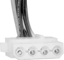
- Peripheral Connector
-
The Peripheral Connector, shown in Figure 26-2, is often called a Molex Connector by technicians. The cable uses a Molex PS-8981-04P or AMP 1-480424-0 connector or equivalent, and 18 AWG wires. Pin 1, at left as you view the connector face, carries +12V and uses a yellow wire. Pins 2 and 3 are COM (ground) and use black wires. Pin 4 is +5V and uses a red wire.
Figure 26-2. Peripheral Connector
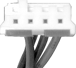
- Floppy Drive Connector
-
The Floppy Drive Connector, shown in Figure 26-3, is often called a Berg Connector, and is also used by some other types of drives (5.25-inch floppy drives use the larger Molex connector also used by hard disks and other drives). The cable uses an AMP 171822-4 connector or equivalent. The wires are 20 AWG. Pin 1, at left as you view the connector face, carries +5V and uses a red wire. Pins 2 and 3 are COM (ground) and use black wires. Pin 4 is +12V and uses a yellow wire.
Figure 26-3. Floppy Drive Connector
|
The number and type of device connectors provided are loosely linked to the form factor and power rating of the power supply. Generally, power supplies with low power ratings and those designed for smaller cases provide fewer device connectors, sometimes as few as three. Power supplies with higher power ratings and those intended to fit large tower cases provide more device connectors, sometimes as many as a dozen. So long as you do not exceed the power supply capacity, you can freely clone device connectors by adding Y-splitters, which are available for a couple of dollars at any computer store.
|
26.3.10 Main Power Switch Power Connectors
Desktop/AT and Desktop/BAT power supplies have a built-in paddle switch to turn power on and off. ATX and ATX-variant power supplies seldom have a physical power switch because they are turned on and off by the motherboard. Some ATX power supplies have a rocker switch on the back of the power supply that disconnects the power supply entirely from mains power. This can be useful because the alternative is disconnecting the power cable when you need to kill all power to the system, including +5VSB, which is ordinarily always present.
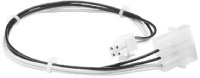
Tower/AT and Tower/BAT power supplies have no built-in main power switch. Instead, they have four power leads that connect to a push-button or toggle switch on the case, as shown in Figure 26-4. These leads, which are usually white, black, blue, and brown, carry AC mains voltage to the power supply.
Figure 26-4. Typical connections for a Tower/AT or Tower/BAT power switch
|
26.3.11 Real-World Power Supplies Compared
Table 26-18 lists the output by voltage of three nominally 350-watt ATX12V power supplies. The PC Power & Cooling Turbo Cool 350 ATX/ATX12V is a premium unit, with a street price of about $65; the Antec SL350 is a name-brand unit that sells for about $45; the Sparkle Power Inc. (SPI) FSP350-60BN is another name-brand unit that sells for about $50. We would like also to have compared a no-name Pacific Rim power supply, but finding technical specifications for such units is impossible, probably because they vary so much from one lot to another that no one bothers to test them.
The three key voltage rails are +3.3V, +5V, and +12V. Note that, although all the power supplies list individual maximum outputs for +3.3V and +5V, they also note maximum combined output of +3.3V and +5V?215W for the PC Power & Cooling unit, 230W for the Antec, and 220W for the SPI unit. Antec is alone, however, in specifying maximum combined output on the +3.3V, +5V, and +12V rails.
|
PC Power & Cooling Turbo-Cool 350 ATX |
Antec SL350 |
Sparkle Power Inc. FSP350-60BN | |||||||
|---|---|---|---|---|---|---|---|---|---|
|
Rail |
+/- |
Amax |
Watts |
+/- |
Amax |
Watts |
+/- |
Amax |
Watts |
|
+3.3VDC |
1% |
28 |
92.4 |
5% |
28 |
92.4 |
4% |
28 |
92.4 |
|
+5VDC |
5% |
32 |
160 |
5% |
35 |
175 |
5% |
32 |
160 |
|
Maximum combined Wattage: 3.3 + 5 |
215 |
230 |
220 | ||||||
|
+12VDC |
5% |
15 |
180 |
5% |
16 |
192 |
5% |
15 |
180 |
|
Maximum combined Wattage: 3.3 + 5 + 12 |
n/a |
330 |
n/a | ||||||
|
-5VDC |
5% |
0.3 |
1.5 |
10% |
0.5 |
2.5 |
5% |
0.3 |
1.5 |
|
+5VSB |
5% |
2 |
10 |
5% |
2 |
10 |
5% |
2 |
10 |
|
-12VDC |
5% |
0.8 |
9.6 |
10% |
0.8 |
9.6 |
10% |
0.8 |
9.6 |
|
Total nominal wattage |
453.5 |
481.5 |
453.5 | ||||||
|
Total deliverable wattage |
416.1 |
352.1 |
421.1 | ||||||
The main differences between these power supplies are as follows:
- Total nominal wattage
-
The most obvious difference is in total nominal wattage. Simply adding the wattages on the individual rails tells us that the PC Power & Cooling and SPI units both total 453.5W, while the Antec is noticeably higher at 481.5W. That measure is meaningless, however, because the wattage deliverable on one rail may be constrained by the amount of wattage being drawn on another voltage rail.
- Total deliverable wattage
-
For all three power supplies, the total deliverable combined wattage on the +3.3V and +5V rails is related. For example, the PC Power & Cooling unit can deliver up to 92.4W of +3.3V and 160W of +5V, but the combined total wattage on those two rails cannot exceed 215W. That means if you happen to be drawing 90W on the +3.3V rail, you can draw at most 125W on the +5V rail, even though that rail is rated for a maximum of 160W. In addition to limiting the combined +3.3V/+5V draw, the Antec unit also limits the combined +3.3V/+5V/+12V draw to at most 330W. Taking these combined limits into account, the PC Power & Cooling and SPI units can both theoretically deliver more than 400W, while the Antec unit is limited to at most 352.1W.
In effect, that means that the Antec is not really capable of delivering 350W unless you can load the +3.3V, +5V, and +12V rails in combination at or very near their maximum ratings. That may not happen with a real-world system. Instead, you may have one or two rails loaded to their individual limits, while another voltage rail has a great deal of reserve. Having a lot of unused +12V, for example, does you no good if what you really need is more +3.3V.
Conversely, the PC Power & Cooling and SPI units are more flexible because they place fewer constraints on combined wattages. Although each of them is capable of delivering more than 400W, they are of course still rated as only 350W power supplies. The difference between them and the Antec unit is that they place no limit on combined +3.3V/+5V/+12V wattage. That means that if a system has a very high draw on +12V (such as a fast Pentium 4 system), the power supply can still pump as much +3.3V and +5V as necessary, within its total 350W limit.

Remember that wattage rating depends heavily on the temperature at which the rating is done. We know that the PC Power & Cooling unit was rated at a realistic 40º C. We have no idea what temperature Antec or SPI used for their testing, but 25º C seems to be the industry standard. A nominal 350W power supply tested at 25º C actually delivers about the same wattage as a 230W power supply rated at 40º C.
- Regulation
-
The PC Power & Cooling and SPI units are both within ATX/ATX12V specifications for regulation on all voltage rails. The Antec unit is not ATX-compliant because its 5% load regulation on +3.3VDC is less stringent than the ATX-required 4%. In practical terms, the Antec unit is likely to function adequately, but its poor +3.3V regulation is cause for concern. The SPI unit is regulated within ATX specifications. The PC Power & Cooling unit meets ATX requirements on every rail and greatly exceeds them on the critical +3.3V rail. Tight voltage regulation is key for system stability, so we know which of these power supplies we'd choose.
A more subtle aspect of nominal wattage is component loading. A premium power supply may deliver its rated wattage while driving its components at only 50% of their rated capacity; a midrange name-brand power supply may deliver near its rated wattage while driving its components at 70% of their rated capacity. A no-name power supply will likely deliver nowhere near its rated wattage, and will drive its components at 100% (or even more) of their rated capacity to do so.
Component loading has two important aspects. First, components driven at a fraction of their rated capacity are likely to exceed their design life significantly, while those driven at (or above) their designed limits are likely to be short-lived. Second, a component that is "loafing" is likely to perform much better than one that is being driven at or above its design capacity. For example, components designed to supply +3.3V and driven at 50% of capacity are likely to supply 3.3V bang-on; those driven at 100% of capacity may deliver 3.3V nominal, but the actual voltage may vary significantly. Unfortunately, short of disassembling the power supply (never a good idea) and checking the number, size, and quality of the components, about the only thing you can do to assure that the power supply you choose uses good components is to buy a good name-brand power supply.
Comparing the full spec sheets for these three power supplies turns up other differences not shown in the table, of varying significance. For example, the hold time of the PC Power & Cooling unit is 20 ms, which is the minimum required for ATX compliance. The hold time of the SPI unit is specified as "16.6 ms minimum" and that of the Antec is unspecified, which means that technically neither of these units is ATX-compliant based on the listed specifications. Similarly, the PWR_OK delay times of the Antec and SPI units are listed as 100 - 500 milliseconds, which is technically within ATX requirements, but far inferior to the specific 300 millisecond PWR_OK delay specified for the PC Power & Cooling unit.
|
In short, there are very real differences between power supplies, even if they have the same nominal rating. The PC Power & Cooling unit is a superb power supply, which will supply clean, closely regulated power even when driven at its rated wattage, and is unlikely to fail even if used 24X7 at its rated output power. The SPI unit is a very good power supply, likely to work reliably in less-demanding applications. The Antec unit is relatively poorly regulated, particularly relative to the PC Power & Cooling unit, and is an appropriate choice only when system cost is a very high priority. (In fairness, we should point out that the Antec SL350 is an economy power supply and that Antec does make better power supplies, including the superb TruePower series.) About the best you can say for no-name units is that power is likely to come out of them, although how much, how well-regulated, and for how long are in doubt.


