5.7 Installing Memory
Installing a SIMM or DIMM module is straightforward. Most recent motherboards automatically detect installed memory modules regardless of the slot they occupy, but it is good practice to fill banks from the lowest numbered to the highest. For example, if the motherboard has three banks, fill Bank 1 only after Bank 0 is filled, and fill Bank 2 only after Banks 0 and 1 are filled.
Some motherboards require larger modules be installed in lower-numbered banks. For example, if the motherboard has three DIMM sockets, Bank 0 is currently occupied by a 32 MB DIMM, and you are installing two 64 MB DIMMs, instead of simply installing the two new 64 MB DIMMs in Banks 1 and 2, you may need to remove the 32 MB DIMM from Bank 0, install the 64 MB DIMMs in Banks 0 and 1, and then reinstall the original 32 MB DIMM in Bank 2.
That rule is not invariable, though. A few motherboards require smaller modules be installed in the lower banks. Some motherboards don't care which module you install in which bank. Best practice is to check the manual before installing memory. If no documentation is available, experiment by moving modules around. If some or all of the memory is not recognized during the boot-time memory check or in CMOS Setup, try rearranging the modules. If all memory is recognized, you can safely assume that you have the modules installed correctly.
|
5.7.1 Installing and Removing a SIMM
- To install a SIMM
-
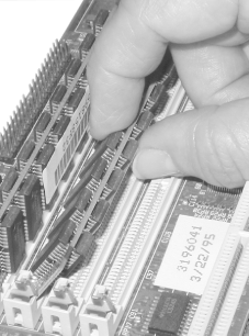
Locate a free SIMM socket of the proper type (30- or 72-pin). One side of the SIMM has a notch that aligns with a matching post on the SIMM slot support bracket, which prevents the SIMM from being installed backward. Align the notch and then slide the contact edge of the SIMM into the SIMM slot at about a 45-degree angle, as shown in Figure 5-3.
Figure 5-3. Inserting the SIMM at a 45-degree angle
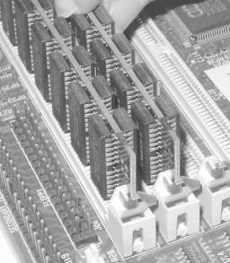
Once you have the SIMM aligned properly, maintain slight pressure toward the slot and pivot the SIMM upward toward the vertical until it snaps into place, as shown in Figure 5-4. Verify that the spring connectors on each side of the SIMM slot bracket have both snapped into the matching holes on the SIMM.
Figure 5-4. Rotating the SIMM to vertical and making sure the locking tabs snap into place
- To remove a SIMM
-
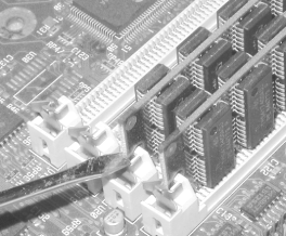
Locate the spring connectors at the top of each side of the SIMM slot bracket and press both of them lightly at the same time while simultaneously pressing the SIMM gently away from the vertical. After the spring connectors release their grip on the SIMM, pivot the SIMM gently downward to about a 45-degree angle and then pull it gently out of the slot. Locking tabs sometimes exert considerable force, so you may find it easier to press the release gently with a small screwdriver, as shown in Figure 5-5.
Figure 5-5. Using a small screwdriver to press down on the locking tabs until they release, while maintaining gentle pressure on the module
|
5.7.2 Installing and Removing a DIMM or RIMM
- To install a DIMM or RIMM
-
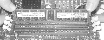
Locate a free socket and pivot the ejector arms on each side of the socket as far as possible toward the horizontal. The contact edge of the DIMM module is keyed with notches that correspond to protuberances in the DIMM socket. Align the notches and slide the DIMM straight down into the socket. Position your thumbs on top of the DIMM at each end and press down firmly, as shown in Figure 5-6.
Figure 5-6. Aligning the memory module and pressing straight down until it seats
The DIMM slides (sometimes snaps) into the socket, which automatically pivots the ejector arms toward the vertical. If the ejector arms are not fully vertical, press them toward the DIMM until they lock into the vertical position, as shown in Figure 5-7. Note that some DIMM sockets have minor physical variations. If the DIMM does not fit easily into the socket, do not force it. Contact the vendor who supplied the DIMM for a replacement.
Figure 5-7. The ejector arms pivoting back to the vertical when the memory module is fully seated
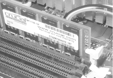

If you are installing Rambus RIMMs, also install a CRIMM in each unused memory slot. Rambus systems malfunction unless all memory slots are occupied, either by a RIMM or a CRIMM. Most Rambus motherboards have enough CRIMMs bundled with the motherboard to populate all but one memory slot. If you run short of CRIMMs, you can buy them at most computer stores.
- To remove a DIMM or RIMM
-
Pivot both ejector arms simultaneously toward the horizontal position. The DIMM simply pops out.
5.7.3 Testing and Configuring Newly Installed Memory
After you install the new memory modules and verify that all is as it should be, apply power to the system. The memory self-test should increment up to the newly installed amount of memory. If it instead shows only the original amount of memory, the cause is almost always that you have not seated the new memory module completely. Power down, reseat the module, and try again.
If the memory check shows an amount of memory larger than the original amount but smaller than the expected new amount, the problem is almost always that the BIOS and/or chipset do not support memory modules of the size you've installed. If that occurs, you may need to do one or more of the following things to resolve the problem:
Check the Chipset Setup portion of CMOS Setup to determine how memory is configured for the newly installed bank(s). Most recent chipsets and BIOSs automatically determine the correct size and configuration parameters for installed modules. But some chipsets, BIOSs, and memory modules do not implement SPD correctly. If this occurs, you may have to set the correct size manually, if indeed the module size you have installed is an available option.
A limitation on maximum module size may be enforced by the chipset, the BIOS, or both. Before deciding you cannot use the larger module, check the motherboard manufacturer's web site for a BIOS update. If the restriction on module size is enforced by the BIOS but not by the chipset, you may find that a later BIOS revision adds support for the larger module.
If all else fails, the only alternative may be to return the memory module (you did make sure you had the right to return an incompatible module, didn't you?) and obtain a smaller module.


