3G Cellular Systems
3G Cellular Systems
In this section we provide a high-level overview of the main 3G systems radio interfaces and their properties. We address CDMA2000 and the evolution of the North American CDMA system to 3G first, and then describe UMTS and the evolution of the GSM system to 3G.
CDMA2000
CDMA2000, often called CDMA 3G, is a next generation of original CDMA IS-95A and IS-95B cellular systems. It has been already deployed in America, as well as some regions in Asia and Eastern Europe. The CDMA2000 Radio Transmission Technology (RTT) includes enhancements that effectively double CDMA IS-95 spectral efficiency, as well as the number of simultaneous voice calls the system can handle. CDMA2000 uses transmission chip rates, which are multiple of 1.2288 Mcps, which means that CDMA2000-based cellular systems are backward-compatible with the large installed base of CDMA IS-95 systems and CDMA2000 mobile terminals can be made compatible with legacy systems. CDMA 2000 deployment can support multiple carrier bandwidths and frequency band plans including PCS and IMT2000. The CDMA2000 RTT support for 1.25-MHz deployment capability is especially important in North America, where it enables CDMA carriers to reuse their existing spectrum to offer CDMA2000 service by only upgrading the equipment without the necessity to buy new spectrum. This version of CDMA2000 had been named CDMA2000 phase one, or CDMA2000-1x RTT. The other version of CDMA2000 technology, called CDMA2000-3x, representing the logical evolution for CDMA2000-1x, employs 5 MHz of bandwidth. [1]
CDMA2000-1x will provide subscribers the ability to transfer and receive packets at raw data rates of 153.6 Kbps or an effective data rate of up to 144 Kbps. CDMA2000-lx, just like its predecessor, provides support for both voice and data. The CDMA2000-1x physical layer incorporates a number of major enhancements that provide for higher data rates and better spectral efficiency than the second-generation CDMA systems. A burst-mode capability is defined to allow better interference management and capacity utilization. An active high-speed packet data mobile always has a traffic channel using a fundamental code. This channel is called the fundamental channel (FCH). An active High Speed Packet Data (HSPD) call with the need for higher bandwidth either in forward or reverse direction could be allocated an additional channel for the duration of a data burst, which is in the order of seconds. The additional channel during this state is called the supplemental channel (SCH), which allows a wide range of data rates; raw data rates of 9.6 Kbps to 307.2 Kbps are supported over each SCH. Though the numerology in the proposed CDMA2000-1x standard supports raw SCH data rates as high as 307.2 Kbps, it is anticipated that the maximum effective data rate that can be supported over a wide area of coverage—with a single 1.25-MHz carrier—will be around 150 Kbps. Usually one SCH is assigned per data service. An SCH with a data rate of 19.2 Kbps or higher is equivalent to multiple voice calls from the consideration of air interface capacity.
CDMA2000-1xEV
To meet the wireless data market requirement for a high-speed, high-capacity solution, the CDMA standard community has developed a data-optimized version of CDMA2000 called CDMA2000-1xEV- DO (where DO stands for Data Only). CDMA2000-1xEVDO supports downlink (to the MS) peak data rates of up to 2457.6 Kbps, and 153.6 Kbps data rate on the uplink (from the MS). Note that while CDMA2000 systems had been designed to provide equal upstream and downstream capacity, the 1xEV DO version of CDMA2000 had been designed to accommodate asymmetric needs of high-speed data users, which require more bandwidth in the downlink direction for downloading information from the Internet and receiving streaming media traffic. Packet data is the only type of traffic currently supported by this technology. Voice over IP support will be added later as the standards mature.
1xEV-DO will provide users with "always-on" packet data connectivity, not unlike current DSL and cable modem offerings. A 1xEV-DO network can be deployed as complementary to a regular CDMA2000-1x network, since most of the hardware components as well as spectrum can be shared between the two. When planning a combined system, you must allocate a separate dedicated 1.25-MHz frequency carrier for 1xEV traffic. While two systems can coexist in a carrier's network, they will require different handsets or two different functionalities supported in one handset in future deployments.
CDMA2000-3x
CDMA2000-3x (or CDMA 3G-3xRTT) uses 5 MHz of bandwidth, and it is therefore classified together with UMTS in the Wideband CDMA (W-CDMA) family of radio transmission technologies. It delivers peak bit rates of up to 144 Kbps for mobile applications and as much as 2 Mbps for stationary applications. CDMA2000-3x will also introduce higher bit rates for data transmission, more sophisticated QoS and policy mechanisms, and advanced multimedia capabilities. It will rely on the ATM-based data link layer between the base stations and MSCs to accommodate the higher speeds and advanced call model. Table 3.2 shows a comparison between the CDMA technologies, including the UMTS W-CDMA technology, which is described in the following section.
|
CALLS PER RADIO CHANNEL |
RADIO CHANNEL BANDWIDTH |
THEORETICAL PEAK DATA RATES |
|
|---|---|---|---|
|
cdmaOne IS-95 (A/B) |
13-28 |
1.25 MHz |
9.6/14.4/19.2 Kbps |
|
CDMA2000-1X 1XEV-DO |
140-200 |
1.25 MHz |
144–153.6 Kbps 144 Kbps - 2.4-Mbps peak |
|
CDMA2000-3X |
180–300 |
5 MHz |
385 Kbps 2.4-Mbps peak |
|
W-CDMA |
140–200 |
5 MHz |
144 Kbps—pedestrian 384 Kbps—vehicular 2.4 Mbps—stationary |
Universal Mobile Telecommunications System
The Universal Mobile Telecommunications System (UMTS) is a third-generation cellular wireless system compliant with all third-generation system definitions. UMTS was designed to be an evolution of the GSM/GPRS system. As a result, UMTS inherits most of the GSM/GPRS core network architecture, and UMTS and GSM roaming and intersystem handover with dual-mode handsets capable of supporting both UMTS and GSM are guaranteed. The UMTS system is defined by 3GPP in three releases: R99, R4, and R5 (see Chapter 4). The UMTS system shares the core network with the GSM system, and from R99 the specifications for the GSM and UMTS core are the same, as mentioned in Chapter 1. Release 99, however, introduces an entirely new radio interface standard based on W-CDMA technology, as well as a new method of interfacing the core to the radio access network (RAN). This chapter provides a brief overview of the UMTS radio interface, while Chapter 4 offers a detailed overview of its core network.
UMTS Standardization
UMTS has been specified by International Telecommunications Union (ITU) in the context of the International Mobile Telecommunications System (IMT-2000) initiative. The 3G Partnership Project (3GPP) was formed in 1998 to coordinate a global effort by a large variety of regional standardization bodies to define the specifications for the UMTS system. The bodies involved in the specification included Association of Radio Industries and Businesses (ARIB) from Japan, Telecommunication Technology Committee (TTC) from Asia, T1P1 from TIA (North America), and European Telecommunications Standards Institute (ETSI) from Europe. ETSI also gave 3GPP the task of maintaining and evolving GSM specifications. This was the logical result derived from the use of the GSM core network as the basis for the development of the UMTS core network specifications and maintaining full roaming and interoperability between GSM and UMTS systems. Network operators and manufacturers also came together to form the Operators Harmonization Group (OHG), which encourages mutual interoperability and roaming between the CDMA2000 and wideband CDMA (W-CDMA) standards—with the ultimate intent, we can predict, to eventually converge to a new globally accepted international standard some time in the future.
UMTS supports the concept of Virtual Home Environment (VHE), which allows subscribers to access the same services from anyplace in the world where UMTS is supported. Subscribers, using the systems supporting VHE, experience the same look and feel of the user interface and will be able to use the same services as in the home network while roaming in any other Public Land Mobile Network (PLMN). The details of the services will largely depend on the capabilities of the visited network and service agreements set up between the various operators. Like its predecessor, the UMTS system offers circuit- and packet-based services. The core networks sections that support these services are called UMTS CS domain and UMTS PS domain. Finally, UMTS offers a core network that is independent from the RAN. This is accomplished by hiding cell level mobility aspects that used to affect the core in GSM inside the RAN. In UMTS, for instance, the core is not aware of the location of the user on a per-cell basis.
UMTS Radio Interface
The UMTS network is logically divided into a UMTS Terrestrial Radio Access Network (UTRAN) and a core network (CN), connected via an open interface (the Iu interface) as shown in Figure 3.5, which depicts a simplified 3GPP reference model. When used to interface with the CS domain, the Iu interface is called Iu-CS, and when it is used to interface with the PS domain, it is called Iu-PS.
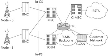 Figure 3.5: 3GPP UMTS architecture.
| Note |
The term UTRAN is used instead of simply URAN because the UMTS system, complying with the IMT-2000 recommendations, was supposed to allow the support of user mobility not only through terrestrial radio equipment (antennas that nowadays we frequently spot on highways and building rooftops) but also through satellite equipment. The terminology reflects this by adding "Terrestrial" to further qualify which access network the UMTS core the specifications refer to. We suspect, a bit cynically, that this other aspect of UMTS might have been safely skipped-given perhaps the less-than-stellar results from the attempts to deploy satellite-based systems. |
From a data service perspective, the GPRS and UMTS PS domains are similar—both allow wireless service providers to offer bidirectional packet data service. The GSM and UMTS CS domains allow for both circuit data support and speech services. The UMTS system allows for higher data rates and multimedia support over the CS bearers, that the GSM did not.
On the high level, UTRAN consists of the Radio Network Controller (RNC) and Node B. RNC is functionally similar to the Base Station Controller (BSC) in GSM networks, although with greater intelligence and a number of new responsibilities because of the fundamental principle of independence of the core from the RAN, which requires the RAN to hide many user mobility support aspects that were originally handled by the core. The RNC manages the radio resource functions, such as call establishment and release, power control, and soft handover. An RNC also triggers the relocation of an MS to another RNC, when it is optimal for an MS to be managed by a new "serving" RNC. This may also involve changing the core network node the MS is homed to, or the CN node may stay unchanged. Two radio interfaces are specified for UMTS: one is a Frequency Division Duplex (FDD) operation using FDD/W-CDMA radio technology, and one is based on a Time Division Duplex (TDD) operation using TDD/W-CDMA radio technology.
UMTS licenses allocate certain frequency bands to operators. One type of allocation is known as paired spectrum. Paired spectrum uses two separate frequency bands, one for uplink and one for downlink traffic. This allocation method is used by the FDD operation. The other type of allocation, used by TDD, is called unpaired spectrum. Here mobile stations send and receive information on the same frequency. Because very fine timing control is required for sending and receiving packets using TDD, this is more suitable for shorter-distance applications, such as the indoor "picocells" that will be installed in places with high user concentration, such as airports, offices, and trade shows.
UMTS will support higher-speed data transfer across the air interface than its parent, the GSM system. It defines three mobility categories with corresponding bit rates:
-
High mobility, such as communication from an automobile or a train with up to a 144-Kbps data rate
-
Low mobility, such as communication while walking, with up to a 384-Kbps data rate
-
Indoor mobility, which is not really a true mobility and constitutes communication while stationary, with up to a 2-Mbps data rate
The actual data rates will depend on the capacity of the air interface and the environmental conditions at any given moment. A larger number of high data rate users at the air interface will substantially reduce the overall throughput they will experience from the peak rates we just listed.
Enchased Data Rates for Global Evolution
Enchased Data Rates for Global Evolution [2] (EDGE) is still considered by some a 2G technology; however, given the latest standardization directions we are about to discuss, EDGE, at least in its next-generation versions, may very well deserve a 3G status. This prompted us to include it under the 3G section of this chapter. EDGE was conceived in 1997 as an evolution path for GSM only, but was later adopted for North American TDMA. The adaptation of EDGE as a possible air interface technology evolution for North American TDMA took place in 1998 when the main TDMA technology industry forum, the Universal Wireless Communications Consortium (UWCC), adopted it as a basis for the 136 high-speed (136-HS) standard to provide 384-Kbps services, which helped to satisfy many of the 3G system requirements.
While EDGE reuses GSM and TDMA spectrum and time slot structure, it is not restricted to GSM channel structure and is based on modern, highly efficient modulation schemes. The EDGE radio technology relies on a fundamental link quality control, a concept that allows for adaptation of data protection to channel quality, thus achieving the optimal bit rate for a variety of radio environments. EDGE modulation schemes allow for the total bit rates from 22.8 Kbps up to 69.2 Kbps per time slot, respectively. A maximum of eight combined channels in the EDGE system with an estimated effective bit rate of 48 Kbps per channel will yield as much as 384 Kbps of total throughput (theoretically up to 473.6 Kbps), which is in line with 3G bit rate requirements for wireless packet data. Basically, EDGE only introduces new modulation techniques, new channel coding, adjustments to radio link protocols, and other enhancements to the existing GSM and TDMA systems without effecting their core networks.
| Note |
EDGE technology provides the evolution path for the GSM and TDMA air interface only, while the packet core infrastructure remains based on GPRS. That's why we have not included EDGE in the following chapters, which discusses core infrastructure and wireless data delivery mechanisms. |
EDGE Classification
A few different flavors of EDGE exist, as shown in Figure 3.6. We will briefly describe each one.
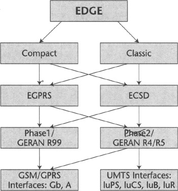
Figure 3.6: Edge taxonomy.
First are the EDGE Compact and EDGE Classic versions. EDGE Compact designed for TDMA IS-136 uses 200-kHz control-channel structure. EDGE Compact allows for data rates of up to 7/8's that of ETSI-defined EDGE classic. It uses synchronized base stations to maintain a minimal spectrum deployment of 1 MHz in a 1 frequency-reuse pattern. EDGE Classic employs the traditional GSM 200-kHz control-channel structure with a 4/12 frequency-reuse pattern on the first frequency.
Second, there is a distinction between EDGE systems deployed for packet-switched data enhancement called Enhanced GPRS (EGPRS) and circuit-switched data enhancement called Enhanced CSD or Enhanced HSCSD (ECSD or E-HSCSD).
Finally, there are two EDGE phases. Phase1, also referred to as GERAN R99, and Phase2, now superceded by the name GERAN R4/R5. EDGE Phase1 defines new air interface capable of up to 384-Kbps packet data throughput and will require smaller cell sizes compared to those of GSM. It also defines single- and multislot packet-switched and circuit-switched services. EDGE Phasel standardization has recently been completed within 3GPP Release 99. EDGE Phase2, which is still under standardization, defines the alignment with UMTS (see next section) under the concept known as GSM/EDGE Radio Access Network (GERAN). In fact, EDGE Phase2, or GERAN R4/R5, will extend all the services and throughput of the Phasel over UMTS core network. To achieve that, the GERAN R4 and R5 standards framework is mostly centered around the advanced services definition similar to UMTS services architecture.
The eventual objectives of GERAN specification include providing classes of data services similar to UMTS and the ability to interface and handover with UMTS CN over an Iu interface. While GERAN R4 introduces only minor enhancements to the current EDGE standard, mostly around the air interface, and retained the interface (Gb) for connection to GPRS, major enhancement packages are expected to come with GERAN R5, which will introduce the UMTS QoS framework, support for the Iu interface and protocol architecture, and other enhancements related to the radio interface.
The Future of EDGE
Designed as a GSM and TDMA enhancement, EDGE will efficiently coexist with the current cellular infrastructures based on time-division multiplexing and potentially can provide a migration path alternative to UMTS. EDGE might be attractive to those wireless operators that were unable to obtain expensive 3G licenses—for instance, in some Western European countries. These operators expect the combination of EDGE and GSM to provide a path to the offering of global roaming and 3G services, while not requiring the acquisition of new spectrum necessary to run a 3G system based on W-CDMA, somewhat similarly to the 3G-1X approach used by traditional CDMA carriers. The migration to EDGE in North American markets is even more likely, because the UMTS spectrum is not available in this part of the world. [3]
[1]Hence the name: 1x for 1.25 MHz and 3x for 5 MHz, which is roughly three times that.
[2]Originally the "G" in EDGE referred to GSM but now is increasingly replaced with Global to be more inclusive and accurate (EDGE is also an evolution path for TDMA). All three terms are still being used, however, depending on who is presenting them.
[3]A different version of UMTS radio interface operating in a frequency different than the European system would be the only way to deploy UMTS in North America unless the spectrum becomes available.


