GSM and UMTS Packet Data: General Packet Radio Service and UMTS PS Domain
GSM and UMTS Packet Data: General Packet Radio Service and UMTS PS Domain
In this section we describe the GPRS and UMTS PS domain systems and document the services offered to the MS. We look at the possible ways an MS can access packet data networks, such as which protocols can be used and in which way user authentication can take place. Also, we outline what the current status of the market is, relative to some capabilities we believe will be adding value to service providers but perhaps are not yet widely offered by most network equipment manufacturers. Finally, we conclude the section with a discussion of services capabilities of the two systems.
GPRS Elements
The GPRS system is a packet data extension of the GSM system, which was originally designed for circuit services. GPRS enables the support of packet-based data transmission over the radio interface and packet data mobility within the core network. Deploying GPRS entails a Base Station Subsystems (BSS) software-only upgrade, which allows multiplexing of data services over the slots not occupied by speech services, flow control, and retransmission mechanisms necessary to deliver data services over the (GSM) radio transmission technology. It also requires updating the HLR software and installing new core network nodes: the Serving GPRS Support Node and Gateway GPRS Support Node (SGSN and GGSN). DNS, address management system, AAA, billing, and intelligent network are additional components that are parts of advanced GPRS services. The GPRS architecture and specifications were defined by ETSI and now are maintained by 3GPP (see Chapter 1). The GPRS architecture is depicted in Figure 4.7.
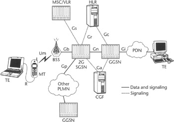 Figure 4.7: GPRS architecture.
The SGSN in GPRS, also referred to as 2G SGSN, offers network layer compression services, segmentation and reassembly functionality, logical link layer framing and multiplexing, ciphering, as well as handling MS signaling and mobility management (within the BSS, between SGSNs), and managing GTP tunnels established toward GGSNs. The SGSN also interacts with the HLR and the intelligent network, the MSC, and the SMS Service Center (SMS-SC).
The GGSN "anchors" the data communications session and provides access to packet data networks by supporting the termination of GTP tunnels from the SGSN to which the MS is currently attached. GGSNs are also used in IP networks to provide a foundation and a gateway to advanced packet data services such as Web browsing, WAP; remote private networks, including networks used to provide mobility support for nonroaming users (intra-PLMN network), roaming (GPRS Roaming Exchange or GRX network), and GPRS network element functions.
UMTS Elements
The UMTS offers packet data services over its PS domain (see the next section). Its architecture, shown in Figure 4.8, is similar to the GPRS architecture. The same network nodes are involved in the core network, although the GTP protocol used in UMTS (GTPvl) is not backward-compatible with the GTP protocol versions used for GPRS (GTPv0). Other differences are in the service capabilities—for instance, UMTS supports its own QoS framework along with more multimedia capabilities. Also, the UMTS SGSN, also referred to as 3G SGSN, does not terminate any link layer protocols nor provide network layer compression or ciphering. Instead, it simply relays packets between GGSNs and Radio Network Controllers over GTP tunnels. (As mentioned in Chapter 3, RNCs are somewhat similar in functionality to BSCs in GSM.) In UMTS, the RNC function is managing mobility of MSs among the Node Bs (UMTS base stations), which it controls transparently to the UMTS PS domain. According to one of the UMTS fundamental principles, the RAN details must be hidden from the core. This is one of the reasons why all the UMTS link layer functionality has been moved from SGSN to the RNC.
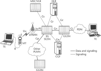
Figure 4.8: 3GPP UMTS architecture.
The system specification for both the GPRS and UMTS PS domain for Release 99, and later releases, is contained in one single document—[3GPP TS 23.060]. It defines all the system-level aspects from 3GPP R99 onward, and it points out the differences between the two systems. Such differences are normally only minor or are related to the handling of terminal mobility management and to interfacing the RAN. In releases before R99, GPRS architecture was specified by [GSM TS 03.60].
GPRS and UMTS PS Domain System Architecture
The GPRS system defines mainly two components: the BSS and the PLMN backbone. The GPRS BSS is the GSM BSS augmented with a Packet Control Unit (PCU) that is used to upgrade the GSM BSS to support packet services. The PLMN backbone includes two new nodes introduced previously: the SGSN and the GGSN. The GGSN and the SGSN are connected via an IP network and interact via the Gn interface, based on the GTP protocol.
When a user roams, that user attaches to a SGSN in the visited network and a GGSN in either the home network or the visited network. If the GGSN is in the home network, the IP network used to connect the visited SGSN to the home GGSN is named the Inter-PLMN Backbone Network. The Inter-PLMN Backbone Network is usually offered by network service providers under the name GPRS Roaming Exchange (GRX), which was defined by the GSM association. Candidates to operate the GRX network have to comply with requirements set forth by the GSM Association. A curious aspect of GPRS as it relates to GRX is that the SGSN in the visited network and the GGSN in the home network interact over GRX network via an interface, called Gp, which is entirely identical from a protocol perspective to the Gn interface. However, since wireless network providers may decide to provide additional security mechanisms to protect inter-PLMN traffic—and will have to do so starting from 3GPP Release 5—it was determined that a new name for the interface was in order, even though such security mechanisms were not standardized.
The UMTS system takes into account from the outset the need of supporting both a packet-switched (PS) core network and a circuit-switched (CS) core network. One of the principles for general 3G access network specifications has been independence of the core network from the radio interface and support of multiple cores. 3GPP has defined a CS domain for circuit services and a PS domain for packet-based services. Since mobility within the UMTS Terrestrial Radio Access Network (UTRAN) must be transparent to the UMTS core, the later should be unaware that the MS would be camped on a particular base station. To stress this need, 3GPP decided that the RAN would be specified as a network made of RNCs and Node Bs, moving away from GSM terminology. Also, early models and research projects introduced the concept of Access Network Operators (ANOs) and of Core Network Operators (CNOs). These concepts did not make it into the official terminology, and standardization efforts did not address their support as officially recognized entities.
The UMTS PS domain core is identical to the GPRS core. In fact, starting from R99, both systems' specifications have no technical differences as far as the core network is concerned. Notably, however, there are some significant differences between the available services in GPRS R98 and GPRS/UMTS R99 that will be highlighted in the remainder of this chapter. We think it is useful remarking the differences between the two systems, because GPRS will be normally identified with R98, since the vast majority of networks will be supporting UMTS only from R99 onward (with the exception of some North American operators who might elect to support EDGE access network, for reasons discussed in Chapter 3).
GPRS specifications define new protocol layers in the BSS—Radio Link Control (RLC) and Medium Access Control (MAC)—that enable the usage of the existing GSM framing structure for GPRS. The GSM system specification allows for the usage of one to eight time slots in both uplink and downlink. The standard specs define the way to adapt different network protocols to the logical link service offered by this system—Sub-Network Dependent Convergence Protocol (SNDCP)—by relaying Logical Link Control (LLC) frames between the MS and the SGSN. This relay functionality is provided by the PCU, which enables enhancements of the GSM BSS to become GPRS services-capable.
The GSM RAN, augmented with the PCU functionality, is connected to the GPRS core via the Gb interface, which defines a Frame Relay-based network service on top of which the base station subsystem GPRS protocol (BSSGP) is carried (Figure 4.9). BSSGP is used to support logical channels on top of the Frame Relay network service. These logical channels are used to implement an LLC protocol frame's routing between the BSS and the core, so that the BSC+PCU can route LLC frames to the correct cell. In the uplink, the BSSGP carries the cell ID information, and any LLC frame transported on the BSSGP protocol can offer location information. Typically, an MS updates the location (cell update) when it is with an active session (sending and receiving data) by sending an LLC frame.
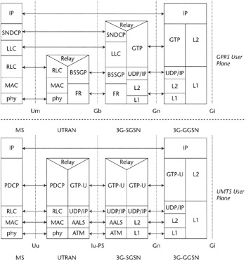
Figure 4.9: The GPRS user plane and control plane.
SNDCP, LLC, and BSSGP—as well as the Frame Relay-based network service—are terminated at the 2G SGSN. Since both user traffic and control information are transported over these protocols, and the link layer services to the mobile are terminated at the 2G SGSN, a 2G SGSN is particularly complex. This complexity potentially brings severe limitations on its scalability. In part to address this situation, during the UMTS standards development, the decision was taken not to terminate link layers at the SGSN, thus reducing the complexity of this element and enabling it to scale to support many more subscribers and a wider coverage area. Scaling an SGSN to cover wider area is important to minimize mobility management signaling associated to handoff and to allow the handoffs to be, on the average, smoother. In UMTS, 3GPP defined a cleaner interface between the RAN and the PS Domain Core network, named the Iu-PS interface (Iu interface in its general form was first introduced in Chapter 3). This interface is based on IP over ATM transport for the user plane (the link layer can be based on any technology starting from releases later than R99, such as R4 and R5), and on the Radio Access Network Application Part (RANAP) protocol for the control plane. RANAP is an SCCP user application. SCCP is carried over a broadband SS7 (MTP3-B, described in [Q.2210] using the service of SAAL-NNI (Signaling ATM Adaptation Layer Network-to-Network Interface) [Q.2100] or an IP transport based on SIGTRAN protocols—namely, M3UA and SCCP.
User packets are transferred over the Iu-PS using GTP/UDP/IP transport, and then relayed by the RNC toward the MS using radio link protocols (PDCP/RLC/MAC). Packed Data Convergence Protocol (PDCP) functionality in UMTS is similar to SNDCP in GPRS. It also supports header compression protocols that are particularly useful for reduction of the overhead for real-time applications—in particular, for future Voice over IP (VoIP) applications that will be characterizing the evolution of the UMTS system as we move to UMTS Release 5. (See Chapter 9 on the system evolution for more details.) The RLC and MAC layers are used to implement the radio link layer. They implement the logical link layer channels over the W-CDMA radio interface physical layer. Figure 4.9 summarizes the discussion on the protocol stacks we have just completed by giving a synopsis of the user plane of both the GPRS and UMTS systems.
The Mobile Terminal communicates control information to the GPRS or UMTS core network using a Radio Interface Layer 3 protocol (RIL3) specified in [3GPP TS 24.008]. This includes GPRS (or packet, in UMTS) mobility management and session management. In GPRS, RIL3 is carried over the LLC NULL channel and is handled by the SGSN on the core network side. In UMTS, this protocol is transported using the direct transfer procedure over the RANAP protocol. The SGSN elaborates control information from the terminal, and as a consequence, it can interact with other entities in the network. For example, it can open MAP dialogues with the HLR for security procedures, subscriber information retrieval, or location update purposes. It also can interact with the intelligent network via the CAMEL [3GPP TS 23.078] interface, for instance, to offer prepaid data services to GPRS users.
Packed data sessions in GPRS and UMTS are established by setting up and maintaining GTP tunnels toward GGSNs. A GTP tunnel is an encapsulation of the user packets between the GGSN and the SGSN in GTP/ UDP/IP. Actually, the encapsulation was also defined to be GTP/TCP/IP, but from R99 onward it was the common consensus that this was not needed, since its only purpose was transferring X.25 in a reliable manner over the PLMN backbone. As is clear now, X.25 is by no means the future of data networking; the wireless carriers aren't going to offer X.25 service, and the networking equipment vendors won't support it.
Another function of the SGSN is the collection of charging data and communication to a Charging Gateway Function (CGF) over the Ga interface (see Figure 4.7). The Ga interface is based on the GTP protocol [3GPP TS 32.015]. The SGSN can also support SMS services via the Gd interface to SMS-GMSC and interact with the MSC/VLR via the Gs interface for paging coordination and combined location update. Because of the limited scope of this book we will not be addressing these aspects of SGSN in more detail. Please refer to the Bibliography if you wish to find articles and Web sites that contain a more in-depth discussion of this subject.
GPRS and UMTS PS Domain Service Capabilities
The GPRS and UMTS PS domain systems are in principle multi-protocol and neutral to the nature of the network layer or link layers of the user traffic. The user protocols are also called Packet Data Protocols (PDPs). The type of protocol is identified with the term "PDP type." Initially, the GPRS system supported many more PDP types than were actually implemented and deployed. For example, 3GPP was recommending PDP type supporting X.25 based on TCP/IP-reliable delivery of GTP-encapsulated X.25 packets over the GPRS backbone. This PDP type was later removed from the specs from R99 onward, and it is unlikely that it will be present in any real deployment of earlier releases. Another example is Internet Host Octet Stream Protocol (IHOSS), which was supporting a transparent stream of octets between GGSN and MS. This PDP type was also removed from the R99 specifications.
GPRS provides support for both IPv4 and IPv6, but IPv6 cannot be realistically expected to see deployment until sometime in 2004. It is supporting PPP type PDP starting from R98, but unfortunately, terminal vendors did not rush to implement the support of this PDP type, and we haven't seen any real support of this PDP type as yet. In fact, we have witnessed an unexpected amount of controversy surrounding this PDP type. Some vendors have tried to remove it from the standard, despite the fact that in principle this PDP type would prove to be beneficial in offering advanced data services such as access to private networks (as described in Chapter 6).
The GPRS and UMTS PS domain systems offer an unreliable transport channel from the GGSN to the MS. This channel can be characterized by a number of QoS parameters, which are different for releases prior to R99 and releases from R99 onward. In R99 and later releases, it is possible to differentiate the handling of packets belonging to the same user session. This is accomplished by establishing multiple bearers (PDP contexts) of different traffic class and QoS profile, associated with the same session, and by forwarding packets on to the appropriate bearers based on some classification rules established at the GGSN and at the MS. This capability has been introduced because of the requirement of offering multimedia capabilities via the UMTS system, at the basis of the service aspects expected from 3G cellular systems. In R98, instead, only one level of QoS (and only one PDP context) can be associated to a session.
GPRS and UMTS PS Domain Terminal
There are three different classes of GPRS MS:
-
Class A. This class allows for concurrent support of GSM and GPRS services.
-
Class B. In this class, the MS monitors both GSM and GPRS paging channels, but only one service can be supported at a time.
-
Class C. In this class, the MS only supports GPRS service (as a data-only device).
Class A terminals require two separate GSM transceivers operating on different frequencies, with independent packet and circuit services. Because of the complexity of such terminals, in R99, operators and manufacturers targeted for the definition of terminals supporting Dual Transfer Mode (DTM). From a service perspective, this approach still offers the simultaneous coexistence of GPRS and GSM voice services like in a Class A terminal, but from a paging perspective they are more similar to a Class B device and require a single transceiver. This approach is made possible via an upgrade of the BSS to route paging over the same channel as used for GPRS, when the MS is GPRS-attached. Note that this enables the paging coordination to happen in the BSS, much like in UMTS systems.
A Mobile Terminal capable of UMTS PS or GPRS access can either be:
-
An integrated device offering computing and wireless data access in one physical unit
-
Composed of two components: one devoted to wireless access and the other a data applications capable device
The latter configuration is similar to today's laptops, which are equipped with PCMCIA modem cards or a serial connection to a modem. In fact, the 3GPP standards [3GPP TS 29.061], [3GPP TS 27.060] define the existence of two logical components of the MS: the Terminal Equipment (TE) and the Mobile Termination (MT). The TE is the computing-capable part of the MS. The MT is the part devoted to the support of the wireless data access capabilities. When the TE and MT are implemented as separate physical entities, they can be connected by multiple technologies (serial, infrared, Bluetooth, etc.) with the link layer based on PPP, or another proprietary interface. Figures 4.7 and 4.8 show the two MS components as separated by the R interface. Indeed, this interface may be internal between components of a single physical package, rather than between physically distinct entities.
When the PPP interface is used between the TE and MT, the IP PDP type can still be used, but the authentication and configuration material is not transported between the GGSN and the MT using PPP. Rather, it is encapsulated in a Protocol Configuration Options Information Element (PCO IE), transparently relayed between RIL3 and GTP by the SGSN. This way, PPP exists between the TE and MT, but not between the MT and the GGSN. This access mode is called nontransparent IP access and is discussed in more depth in Chapter 6.
Mobile Terminals also often come with dual-mode GPRS/GSM and UMTS capability, since many operators will roll out UMTS starting from densely populated and capacity-strained areas, and rely on GPRS for the handling of users in areas where only 2G coverage exists. In fact, this will be one of the most commonly requested terminal features in the early days of UMTS.


