Network Services
Network Services
The operation of a service provider or enterprise network, including VPNs, entails some configuration and management challenges that are resolved via a set of tools, protocols, and devices. This section provides a brief overview of the operational issues and the way these are resolved via a set of tools assembled under the umbrella of network services.
Address Management
One task that can really burden an IT administrator is assigning IP addresses to hosts. This is challenging because in assigning addresses there are constraints related to topology, and these constraints become even more challenging as the users become mobile and do not keep stationary in the same network more than a few minutes or hours. Also, the IT administrator must be mindful about conflicts between private and public addressing schemes and the use of public IP addresses in general, which recently turned into an expensive resource in short supply. So an administrator must be able to avoid conflicts and also conserve IP addresses in large deployments. Static address management does not allow for conserving IP addresses; therefore, dynamic address assignment methods must be applied. However, when dynamically assigning IP addresses, ways to check that the same IP address is not assigned to more than one user at the same time must exist.
Another problem frequently affects network administrators: Networks that do not exchange routing information, such as a private network and a public network, or a pair of private networks possibly using overlapping private addresses spaces, sometimes still need to exchange traffic. This is typical of enterprise private networks providing access to the Internet or other private networks that belong to business partners or to companies that have been recently acquired. This common problem is resolved by the use of Network Address Translation, which we address at the end of this chapter.
Of course, as the number of IP hosts in a network increases into the hundreds, the complexity of manually managing the dynamic assignment of IP addresses becomes so high that no human can reasonably be devoted to this task. This situation was at the root of the definition of the Dynamic Host Configuration Protocol (DHCP), which is commonly used in enterprise and campus networks to assign IP addresses to hosts and configure hosts with other information necessary to use the IP network services. There are other ways to dynamically assign IP address to terminals, such as the IPCP mechanism in PPP, but in this section, we concentrate on DHCP since it is the most widespread method used by landline computer networks based on shared medium and is expected to play a similar role in wireless data networks such as Wireless LANs. Another popular alternative to DHCP is PPP-based dynamic address assignment. In this method, the NAS manages local pools of IP addresses and assigns them to hosts during PPP session establishment, or the NAS dialogues with a DHCP server acting as a DHCP client on behalf of the host. It is also possible that the AAA infrastructure hands out the IP address to the NAS. Possibly, the AAA server in turn acts as a DHCP client.
DHCP Protocol
The DHCP protocol, defined in [RFC2131], is a client/server protocol that allows for configuring IP hosts with an IP address and other information such as the DNS server IP address and the default gateway IP address. The protocol allows configuring an IP host without the need to have any previous knowledge of the networks where it is located. As depicted in Figure 2.15, the host's DHCP client simply sends some broadcast DHCP packets in an attempt to communicate with any DHCP server on the link where the node is attached (DHCP DISCOVER messages). Note that any router should be configured not to forward broadcast packets, but routers that are used to support DHCP—that is, routers that offer DHCP relay services—can forward DHCP queries by relaying properly modified DHCP packet onto the same subnetworks for high availability deployments. They respond via DHCP OFFER messages, each containing a server identifier. The client receives the offers and selects one of them to use. It then responds with a broadcast DHCP REQUEST message containing the Server Identifier. Servers that are not identified by the Server Identifier abandon the transaction, while the identified server may unicast a DHCP ACK message back to the client accepting the IP address, or it sends a DHCP NACK, which notifies the client that the configuration information is out-of-date and a new configuration attempt should be started. This is useful to implement the lease time feature, as well as to notify clients of any inconsistent notion of configuration information with what the server assumes. A DHCP client may also release an IP address it no longer uses by issuing a DHCP RELEASE message toward the DHCP server the host has "leased" the IP address from.
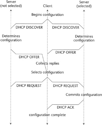 Figure 2.15: DHCP protocol-based IP address assignment.
Also, as mentioned, DHCP may be used to configure hosts with generic information via the DHCP INFORM message the client sends to the server to get additional configuration information we do not specify here—for instance, application-level configuration information. The DHCP server responds to the INFORM message via a DHCP ACK containing the configuration information in the DHCP options requested in the DHCP INFORM message by including them. The INFORM message can be unicast to the DHCP server directly when its address is known in advance (as in the case when the host previously obtained the IP address via DHCP). Otherwise, a host can broadcast this message looking for any DHCP server to respond, which would normally happen in wireless systems when the IP address was assigned by other means or when a PPP-based host requires configuration information the Network Control Protocol (NCP) cannot deliver.
Host Naming
One of the problems that used to affect network administrators was the need to identify an IP host via an identifier that can be easily used by a human. In fact, typing the IP address of a host is a more difficult task than writing a readable alphanumeric label, which can be semantically associated with something. Also, a mnemonic label is much more human-friendly, and since humans are the users of applications that need a host identifier as input, it makes sense to use those to identify hosts. However, this poses the problem of how to manage the mapping between the labels and the IP addresses, which in the end are what the application needs to address the IP hosts using IP packets. This drove the definition and deployment of a distributed database system that allows for a global IP hostname resolution infrastructure, called the Domain Name System (DNS).
Domain Name System
The Domain Name System is a distributed database system that allows for global resolutions of hostnames to IP addresses. As illustrated in Figure 2.16, the name of a host is organized according to a syntax, described in detail in [RFC1034], that defines the hostname to be made of structured labels, made of alphanumeric strings separated by a dot. This notation is know as a fully qualified domain name (FQDN) and is in the form label1.label2. ... .Label(T-l).labelT. LabelT is named a Top Level Domain (TLD), and it can be a country code (e.g., us, fr, uk, it) or one of the standard TLDs allowed for the Internet—traditionally, com, mil, gov, org, net, but more recently biz, int, nu, and others are being defined. Label (T-1) is defined as a domain, and it identifies uniquely an administratively independent namespace for which the owner of the domain has the right to define hostname-to-IP address mapping by defining an additional label value to be prepended to Label (T-1). An entity administering a domain may define the domain to be made only by a single name—for instance, bigco.com—that would map to one or more IP addresses. Alternately, the domain may be made by hundreds of hostnames obtained by adding additional dot-separated labels to the two labels identifying the domain name.
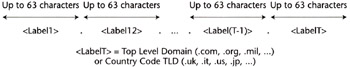
Figure 2.16: Sample hostname structure.
This apparently germane notation has its roots in the operation of the DNS distributed database. The DNS in fact is made of a root zone, which in turn is made of 12 servers that store the IP address of servers that can resolve the hostname of hosts belonging to each and every DNS domain. When a host attempts to resolve a hostname to an IP address, as depicted in Figure 2.17, it first looks up an optional internal cache. Most likely, this results in no resolution, and therefore a query is performed to a server configured for the local network. This query may fail as well—and in most cases it does, since the served names are only those associated to the IP addresses administered by the local network operator, for instance, by a certain ISP. When this happens, the DNS client on the host queries the TLD server, which points to the address of the server that can resolve the host-name. The client then can query this address and obtain from it the desired information. Normally, a single IP address is returned, but multiple IP addresses can be returned as well. The host that obtains such a list of IP addresses can use any of them to communicate with the desired server. These multiple IP addresses may be associated to IP interfaces of a single physical machine or multiple computers. It should also be noted that the DNS allows for the resolution of hostnames in at most three steps.
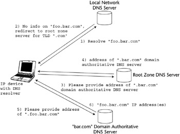
Figure 2.17: DNS query for hostname resolution.
It is also possible to query the DNS to find out what is the hostname associated to an IP address, without entering technical details. This functionality might be useful because a host may be able to verify the hostname of a correspondent, for instance, to check that it really belongs to a domain that has access rights to some resources. However, this feature is not often used, mainly because not every domain is configured to provide this service.
Lastly, it is worth mentioning that an organization operating a private network can define its own private DNS and its own private root zone servers serving proprietary TLDs. This is in fact the approach followed by the GSM association when they defined the .gprs TLD to be used in GPRS systems to construct FQDNs used to identify the IP address of points of termination of GTP tunnels at the GGSN. These points of termination are also known as access points, and hence the identifiers are known as access point names, or APNs. Following is the syntax of an APN:
  APN =-<APN Network Identifier>. <APN Operator Identifier>

  <APN Network Identifier> = Any valid DNS name
  < APN Operator Identifier> = -<mnc<MNC>.mcc<MCC>.gprs
  or -<wireless operator domain name>.gprs

  <MNC> = Mobile Network code belonging to the operator

  <MCC>= Mobile Country code of the Country where the operator is based
Network Address Translation
Network Address Translation (NAT) is a mechanism that allows networks belonging to two independent routing and addressing realms—that is, networks that may use different or overlapping addressing schemes that are not mutually reachable based on end-to-end IP routing—to exchange traffic. For instance, the two networks may be a corporate network using a private addressing scheme and an ISP network using public addresses, or a corporation and a business partner networks both using overlapping private address space. NAT is specified by a number of IETF RFCs, such as [RFC3022] defining NAT, and [RFC2709] describing coexistence of NAT and IPSec. As defined in [RFC3022], NAT provides mapping of IP addresses from different groups transparent to the end users or their correspondents. For example, the service provider can map its private IP addresses onto publicly routable (valid) IP addresses whenever the customer needs to connect to the Internet. Technologies like NAT are needed when internal private IP addresses cannot be used outside private networks in a public addressing space either for security or compatibility reasons. The motivation behind the use of NAT is a better utilization of public IP addresses, a high-demand resource.
There are two variations of traditional NAT:
-
IP Network Address Translation, also called Basic or Static NAT
-
Network Address Port Translation (NAPT), also referred to as Port Address Translation (PAT)
NAPT may map multiple IP addresses to a single IP address but with different TCP port numbers. In addition, a method called NAT Protocol Translation (NAT-PT) has been proposed for translating between IPv4 and IPv6 addresses. The migration to IPv6 will be slow, and the networks will coexist for a number of years. During the transition period from IPv4 to IPv6, NAT-PT will probably be used for address translation between networks using these two protocols.
NAT works by modifying IP packet addresses so that the device doing the NAT rewrites the address headers for passed packets according to network-specific address translation rules. The packets are then routed according to the newly written header information. This restriction of remote users' access has become a major problem with VPN implementations. The reason lies in the incompatibility of NAT and IPSec, a mainstream end-to-end encryption and security technology used as a basis for many VPN services. One of the functions of IPSec is supporting end-to-end integrity of user data traffic and sometimes of the IP header (when AH is used). This means that IPSec prevents any modifications to the packet. Since the main function of NAT is to change the destination addresses of IP packets, a NAT process from the IPSec gateway and client point of view will be seen as a violation of end-to-end user data integrity and security. This can potentially disrupt end-to-end tunneling, which can have devastating consequences for voluntary VPN services. As a result, when an IPSec tunnel is established over a network implementing NAT, IPSec packet authentication will fail. Also, IKE suffers from the presence of NAT, since in IKE negotiation, parties exchange their IP address as well.
Let's consider how different modes of IPSec can coexist with NAT. In IPSec transport and tunnel modes, AH authenticates the whole IP packet, including the header. When a NAT device changes IP packet addresses, the new checksum will not be valid and the packet will be discarded at the destination. This makes IPSec AH and NAT incompatible. Contrary to AH, ESP in transport mode protects only the TCP/UDP header of the packet and not its source and destination addresses. So, in this mode the end-to-end integrity of all but TCP/UDP packets passing through NAT will not be violated. The only remaining option is ESP in tunnel mode, for which a number of solutions have been recently proposed to IETF.
One way to solve this incompatibility problem in general is based on the assumption that an NAT device is trusted by an end-to-end security association or an end-to-end tunnel will be replaced by a set of two or more tunnels concatenated or chained at NAT device. This is a simpler solution to a problem, which unfortunately somewhat defeats the purpose of end-to-end tunneling. Another approach that has been recently proposed to IETF is called NAT Traversal or NAT-T. NAT Traversal does not violate basic IPSec architecture, and it is fully compatible with standard IPSec devices. The only requirement for NAT Traversal support is the implementation of a set of capabilities, which must be supported by the devices representing tunnel endpoints and is not affecting any other devices on the data path. If during the IPSec tunnel establishment phase it is detected by the tunnel endpoints that NAT-T is supported and required, the traffic of each negotiated IPSec security association will be encapsulated in UDP packets containing the information that would help to restore the packet changed by NAT into its original form at the tunnel endpoint. The IPSec traffic between the tunnel endpoints is encapsulated in UDP using the IKE port (UDP port 500). As a result, the encapsulated packets follow the same route as IKE packets, which allows for easy firewall traversal and ensures that the modification to the packets done by NAT is similar to modification done by IKE. The original IP header length and protocol type is stored in the NAT-T header.
NAT Traversal had been proposed to IETF by SSH Communications and a coalition of Cisco Systems, F-Secure, Microsoft, and Nortel Networks. Despite still being an Internet Draft at the time of writing, this solution is already being implemented by the industry mostly because of increasing demand from the service provider community and enterprises for which NAT-T allows to establish end-to-end VPNs even if the service provider uses private addressing schemes. The control of the equipment may present a problem, as there is no way to be certain that the owners of the endpoints of the IPSec connection have any control over the equipment between the endpoints. NAT Traversal presents an easier and a much more elegant way to circumvent the problem, since it requires no changes to intermediate NAT devices—which, as stated earlier, may even be outside the control of the operator.


