VLANs
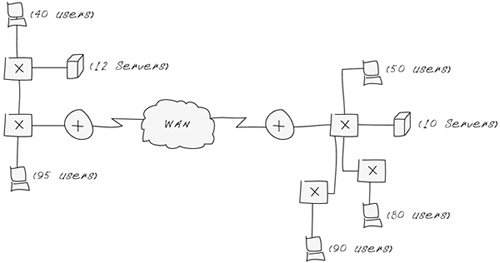
Your network is humming along with no issues and all is well with the world when you meet a friend for lunch. Over sandwiches and salads, your friend asks for your help with their network because users are screaming and performance could be better. Your friend draws the network diagram in Figure 12-13 on a napkin.
Figure 12-13. Network on a Napkin

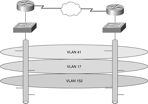
Your friend explains that there are three user communities spread across the two offices, and they are connected by a Frame Relay WAN link, which is always congested and causes users to suffer long delays in transferring files back and forth. You explain to your friend the concept of VLANs, and how implementing VLANs here will help cure the network congestion by putting each user community into its own virtual LAN, so that it doesn't have to share LAN resources with users outside its community, as illustrated in Figure 12-14.
Figure 12-14. VLANs

You show your friend that by using VLANs, each user community has its own broadcast domain that does not interfere with the broadcast domains belonging to the other user communities. Because what you've suggested breaks up the broadcast domains, your friend's users should see a noticeable improvement in network response time, because each LAN is not being saturated with local broadcasts; only the users within each VLAN will see their respective broadcasts.
After you've explained VLANs, your friend thanks you and buys you lunch.
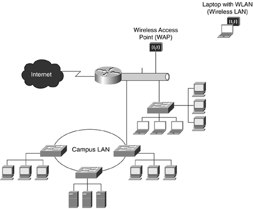
Figure 12-15 illustrates a larger-scale switch-based network with the following characteristics:
The router provides connectivity to the Internet for all connected users.
The Ethernet segment connected to the router is connected to two switches and a wireless access point (WAP). The WAP provides wireless access to the computers capable of wireless LAN (WLAN), such as a user laptop.
One of the two switches connected to the Ethernet segment supports users located in the same building as the router and segment where the other switch supports a campus-area network (CAN). The CAN connects switches housed in different buildings, each switch supporting either end users or servers.
Figure 12-15. Complex Switch-Based Network


