Ethernet LAN Equipment
Chapter 3, "Local-Area Networking Introduction," discussed the different types of hardware found in a LAN environment. The following discussion addresses the suitability for different environments of various types of hardware?hubs, bridges, and switches?and how each piece of hardware functions specifically in an Ethernet environment.
Repeaters?Layer 1 Devices
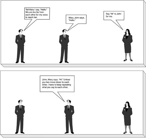
To begin this discussion, it is useful to review the definition presented in Chapter 3: A repeater is a network device used to regenerate or replicate a signal. Repeaters are used in transmission systems to regenerate analog or digital signals distorted by transmission loss. Repeaters are used in both local-and wide-area networking environments to extend the distance a signal can reach. For example, you might use a third person repeating your words to carry your message across a large room, as shown in the Figure 5-3.
Figure 5-3. Two-Person Conversation with a Third Person Repeating
In the LAN environment, you would use a repeater to extend the distance a data signal can travel on a cable, as illustrated in Figure 5-4.
Figure 5-4. Repeater Operation
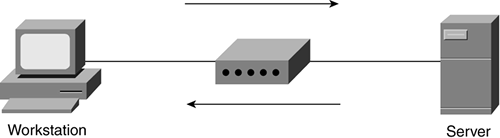
If you are in a large building and you are connecting two network devices that are several hundred feet apart (a server and a workstation, for example), a single 25-or 50-foot cable segment is obviously not going to be long enough. You can use a repeater to connect multiple cables together to make a single cable length long enough for your requirement.
Hubs?Layer 1 Devices
As mentioned in Chapter 3, a hub is often used to connect small LAN segments in which the number of devices is generally 24 or fewer, and hubs are multiport repeaters. Hubs are used to create collision domains, in which all devices on the network can see each other. In larger designs, signal quality begins to deteriorate as segments exceed their maximum length, often a couple hundred feet. Hubs provide the signal amplification required to allow a segment to be extended a greater distance. A hub takes an incoming signal on any one port and repeats it out all ports to enable users to share the Ethernet network resources.
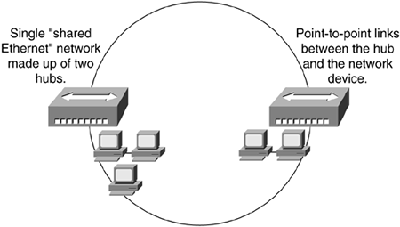
Ethernet hubs create star topologies in 10-Mbps or 100-Mbps half-duplex Ethernet LANs. It is the hub that enables several point-to-point segments to be joined together into one single network, and it is this network of hubs that makes up a shared Ethernet, just as several point-to-point roads join together into the single large network of roads you use to get around town.
A shared Ethernet LAN means that all members of the network are contending for transmission of data onto a single network (collision domain); individual members of a shared network get only a percentage of the available network bandwidth, as illustrated in Figure 5-5.
Figure 5-5. Shared Ethernet (Total Bandwidth Shared Among Attached Hosts)
One end of the point-to-point link is attached to the hub, and the other is attached to the network device, such as a computer or printer. Connecting multiple hubs together expands the shared Ethernet segment but puts more stress on the line's bandwidth because now more users are trying to use the same bandwidth. This is similar to building a new neighborhood without adding roads and thus putting stress on existing roads. As you and your car sit stuck in traffic, so might your data suffer in network congestion.
Network bridges are one way to prevent this congestion. Network bridges function like hubs in that bridges provide a network connection; however, bridges preserve the separation of these network segments by keeping network traffic local to its respective segment instead of repeating it all to the world. Bridge operation is discussed in detail in the following section.
Bridges?Layer 2 Devices
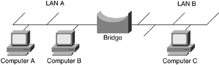
Repeaters and hubs have no intelligence; they just repeat whatever signal is received from one port out all ports without looking at what is being sent or received. Bridges add a level of intelligence to the network by using the MAC address to build a table of hosts, mapping these hosts to a network segment and containing traffic within these network segments. For example, Figure 5-6 illustrates a bridged network with two network segments.
Figure 5-6. Bridge Connecting Two Ethernet Segments
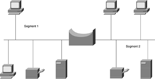
Segments 1 and 2 contain two workstations each, a file server (for file sharing) and a network printer. Suppose that your engineering and financial teams share a floor in an office building and that Segment 1 is made up of your engineering team and Segment 2 is made up of your financial team. If a hub were used to connect these teams to your corporate network, each team would be contending for the total network bandwidth, causing slowdowns on the network. The engineering team might be using all the bandwidth at the moment that someone in finance is trying to process the payroll.
As you might surmise, using a hub in this scenario is not the preferred method because of the contention for the network bandwidth. In this scenario, a bridge is a better choice than a hub because the bridge segments the network into two smaller parts?an engineering team segment and a financial team segment?keeping traffic local to its respective segment.
Ethernet bridges map the MAC addresses of the network devices, or nodes, residing on each network segment. Bridges allow only necessary traffic to pass through the bridge, such as traffic destined for a segment other than the source. When a frame is received by the bridge, the bridge looks at the frame header and reads the source and destination MAC addresses, determining the frame sender and destination. If the frame's source and destination segments are the same, the frame is dropped, or filtered by the bridge; if the segments differ, the bridge forwards the frame to the correct segment.
Figure 5-7 illustrates a small bridged network with three network segments.
Figure 5-7. Bridge Connecting Three LAN Segments
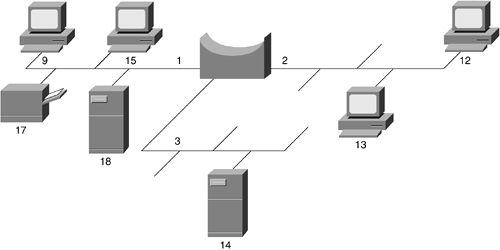
If the bridge sees a frame arrive on port 1 from Host 9, the bridge concludes that Host 9 can be reached through the segment connected to port 1. If the same bridge sees a frame arrive on port 2 from Host 12, the bridge concludes that Host 12 can be reached through the network segment connected to port 2, as illustrated in Figure 5-8. Through this learning process, bridges build a table, such as shown in Table 5-2.
Figure 5-8. Bridge Connecting Two LAN Segments (A and B)
Host Address | Network Segment |
|---|---|
15 | 1 |
17 | 1 |
12 | 2 |
13 | 2 |
18 | 1 |
9 | 1 |
14 | 3 |
This filtering or forwarding function is similar to what an organization's mailroom does on receipt of an envelope; if the destination of the envelope is the same as the source (within the building), the mailroom attendant filters this envelope from any outgoing mail being forwarded to the post office. If this envelope is for a destination outside of the building, the mailroom attendant forwards it to the network, and in this case, the network is the post office.
Bridge Operation
The most frequently used bridge in Ethernet LANs is the transparent bridge. The bridge is called "transparent" because the computers using a bridge are unaware of its presence in the network, and traffic passes "transparently" over the bridge. Think how often you barely notice a small bridge you drive across; if it weren't for the view, you would not know you passed over a bridge because the road continued onward.
LAN bridges forward frames from one LAN to another. For example, as illustrated in Figure 5-8, the bridge forwards all traffic originating from LAN A to destinations found in LAN B, such as Computer C.
The bridge could forward all frames it receives but in doing so it acts as a repeater, not a bridge. The desired operation is for the bridge to forward only frames that need to travel from one LAN to another, such as from LAN A to LAN B and vice versa (as shown in Figure 5-8). In forwarding traffic between LAN segments the bridge learns the following: which computers are connected to which LANs, which addresses to use when forwarding traffic on to another LAN segment, and which addresses to filter or not forward.
To learn which addresses are used and by which ports, the bridge examines the headers of received Ethernet frames on each port in use. The bridge is looking specifically at the source MAC address of each received frame and recording the port on which it was received. A bridge stores the hardware addresses observed from frames received by each interface and uses this information to learn which frames need to be forwarded by the bridge. Figure 5-9 shows this bridge-learning process.
Figure 5-9. Operation of a Bridge Filter Table
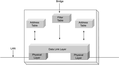
The learned addresses are stored in the interface address table associated with each port (interface). As this table is being built, the bridge examines the destination MAC address of all received frames. As it examines the frames, the bridge searches the interface table to see whether a frame has been previously received from the same address, such as a frame with a source address matching the current destination address.
The bridge's search of the interface table can encounter the following circumstances:
If the address is not found, no frames have been received from the source.
The source may not exist, or it may not have sent any frames using this address. (The address may also have been deleted by the bridge because the bridge was restarted or ran short of address entries in the interface table or the address was too old.)
Because the bridge does not know which port to use to forward the frame, it sends the frame out all ports, except that port from which the frame was received; this is called flooding.
note
It is unnecessary to send the frame back to the same cable segment from which it was received, because any other computer/bridges on this cable will already have received the frame. |
If the address is found in the interface table and is associated with the port on which it was received, the frame is discarded because it is considered to already have been received by the destination.
If the address is found in the interface table and is not associated with the port from which it was received, the bridge forwards the frame to the port associated with the address.
note
Interface Table Management A bridge might implement an interface table using a software data structure or use a content-addressable memory (CAM) chip. In either case, the size of the table is finite. In a large LAN, this limit might be a problem in that there could be more hosts and addresses than there is space in the table. To help keep the table small, most bridges maintain a check of how recently each address was used. Addresses that have not been used for a long period of time (minutes) are deleted. This has the effect of removing unused entries; if the address is used again, however, before a frame is received from the same source, it requires the frame to be flooded to all ports. A useful side effect of deleting old addresses is that the bridge interface table records only working MAC addresses. If a network interface card (NIC) stops sending, its address is deleted from the table. If the NIC is subsequently reconnected, the entry is restored; if the connection is made to another port (the cable is changed), however, a different (updated) entry is inserted that corresponds to the actual port associated with the address. (The bridge always updates the interface table for each source address in a received MAC frame. Therefore, even if a computer changes the point at which it is connected without first having the interface table entry removed, the bridge still updates the table entry.) |
Switches?Layer 2 Devices
Hubs create a network environment in which each connected device shares the available network bandwidth with other devices contending for the same network resources, as illustrated in Figure 5-10.
Figure 5-10. Shared Network
The hub is connecting six workstations together, each sharing the network bandwidth. A finite amount of network bandwidth is available. For example, 10BASE-T Ethernet provides 10 Mbps, and the more workstations added to this network, the less bandwidth available for each. Switches address the shared bandwidth issue and eliminate contention by dedicating a path between the source and the destination, as illustrated in the Figure 5-11.
Figure 5-11. Dedicated Network
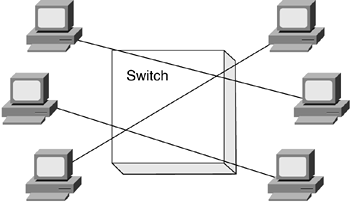
Network switches replace shared-media hubs, increasing network bandwidth. For example, a 16-port 100BASE-T hub shares the total 100-Mbps bandwidth with all 16 attached nodes. By replacing this hub with a switch, each source (sender) and destination (receiver) pair has access to the full 100-Mbps capacity of the network. Each port on the switch can give full bandwidth to a single server or client station or each can be connected to a hub with several stations, as illustrated in Figure 5-12.
Figure 5-12. Switch with Dedicated and Hubbed Nodes
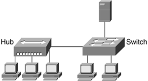
Dedicating ports on Ethernet switches to individual nodes is another way to speed access for critical computers. Servers and power users can take advantage of a full segment for one node, so some networks connect high-traffic nodes to a dedicated switch port.
Switches sit in the same place in the network as hubs. Unlike hubs, however, switches examine each frame and process the frame accordingly instead of just repeating the signal to all ports. Switches map the MAC addresses of the nodes residing on each network segment and then allow only the necessary traffic to pass through the switch. A switch performs the same functions as a bridge; so when the switch receives a frame, it examines the destination and source MAC addresses and compares them to a table of network segments and addresses. If the segments are the same, the frame is dropped, or filtered; if the segments differ, the frame is forwarded to the proper segment.
The filtering of frames and regeneration of forwarded frames enables switches to split a network into separate collision domains. Frame regeneration enables greater distances and more network devices, or nodes, to be used in the total network design, and lowers the overall collision rates. In switched networks, each segment is an independent collision domain, whereas in shared networks all nodes reside in one, big, shared collision domain.
Switch Operation
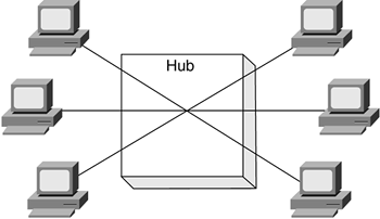
Remember that a bridge with more than two ports can also be called a switch. The difference between a hub and a bridge/switch is the number of frames they forward. Figure 5-13 illustrates how a hub forwards a frame received from Node A that is destined for Node F.
Figure 5-13. A Hub Repeating a Frame from A to F
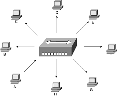
Recall that a hub is a multiport repeater and repeats any signal received on one port out all ports. When the hub receives a signal from Node A, it repeats, or forwards, this received frame out all the ports, so that the frame reaches all connected equipment, even though the frame might be destined for a device connected to one specific port interface (Node F, for example, in the case of Figure 5-13).
Instead of repeating the frame out every port, the switch forwards the frame to only the required interface, as illustrated in Figure 5-14.
Figure 5-14. Switch Forwarding a Frame from A to F
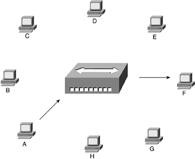
The switch learns the association between the node's MAC address and the interface port in the same way a bridge learns?by listening to which MAC addresses enter the switch and from which port. By sending the frame only where it needs to go, the switch reduces the number of frames on the other LAN segments, in turn reducing the load on these segments and increasing the performance of the connected LANs.
If the switch does not have an entry in its forwarding table and forwards a frame out every port, this is known as a broadcast. This scenario makes it possible to have a flood that is similar to a flood in a hub-based environment. A switch will perform a directed transmission, if it knows the port, and therefore does reduce broadcasts, but a switch does not remove all broadcasts. Because a switch does not remove all broadcasts, a router is used in network designs because a router breaks up broadcast domains and reduces broadcast storms.
Switching Methods
Ethernet switches are an expansion of Ethernet bridging in that switches can link several LANs together. In linking several LANs together, switches forward frames between these LAN segments using one of two basic methods: cut through and store and forward.
Cut-through switches examine only the frame's destination MAC address before forwarding it on to its destination segment. Cut-through switching is comparable to the postmen taking each piece of mail received at a post office, looking at the address, and then sending the mail on to its destination.
Store-and-forward switches accept the entire frame, analyze it for errors, look at the destination MAC address, and then forward the frame on to its destination. Store-and-forward switching is comparable to postmen taking each piece of mail received at the post office, opening it, checking the contents for spelling, grammar, and ensuring no contents are missing, before sending the mail on to its destination. It takes more time to examine the entire frame, but store-and-forward switching enables the switch to catch certain frame errors and keep them from propagating through the network.
Both cut-through and store-and-forward switches separate networks into collision domains, allowing network design rules to be extended. Each of the segments attached to a switch has a full bandwidth shared by fewer users, resulting in better performance, in contrast to the bandwidth sharing that is characteristic of a hub-based environment. A network composed of a number of switches linked together is called a collapsed backbone network.
note
Connecting Bridges and Switches Together A special rule controls bridge and switch interconnection. The rule says that a bridge/switch/hub LAN must form a tree, and not a ring. This means there must be only one path between any two computers. If more than one parallel path exists, a loop would be formed, resulting in endless circulation of frames over the loop. This network loop would result in network overload. To prevent this from happening, the IEEE has defined the spanning-tree algorithm (STA) in IEEE 802.1d, which detects loops and disables one of the parallel paths. The STA might also be used to build fault-tolerant networks, because if the chosen path becomes invalid due to a cable/bridge/switch fault and an alternative path exists, the alternative path is enabled automatically. |
Switches address OSI model Layer 2 (data link) networks, moving frames around based on the hardware, or MAC, address, but switches are limited in their use in that they are LAN devices. Switches do not provide wide-area network (WAN) connectivity. To connect your LAN to another LAN through some outside network, such as the Internet or corporate WAN, a router is needed.
Routers?Layer 3 Devices
Routers are devices that forward data packets from one LAN or WAN to another. Based on routing tables and routing protocols, routers read the network address in the packet contained within each transmitted frame. Routers then select a sending method for the packet based on the most expedient route. This most expedient route is determined by factors such as traffic load, line quality, and available bandwidth. Routers work at Layer 3 (network) in the protocol stack, whereas bridges and switches work at Layer 2 (data link).
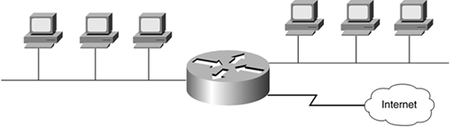
Routers segment LANs to balance traffic within workgroups and to filter traffic for security purposes and policy management. Routers also can be used at the edge of the network to connect remote offices, across WANs or the Internet, as illustrated in Figure 5-15.
Figure 5-15. Router Connecting Two LANs to the Internet
Because routers must examine the network address in the packet, they do more processing and add more overhead than bridges and switches, which both work at the data link (MAC) layer.
Router Operation
A router is essentially a computer with two or more NICs supporting a network protocol, such as the Internet Protocol (IP). The router receives packets from each network interface and forwards these received packets to an appropriate output network interface. Received packets have all data link layer (OSI Layer 2) protocol headers removed, and transmitted packets have a new link protocol header added before transmission.
The router uses the information held in the network layer header, such as an IP address, to decide whether to forward each received packet, and which network interface to use to send the packet. Most packets are forwarded based on the packet's network destination address, along with routing information held within the router in a routing table, as illustrated in Figure 5-16.
Figure 5-16. Router Architecture
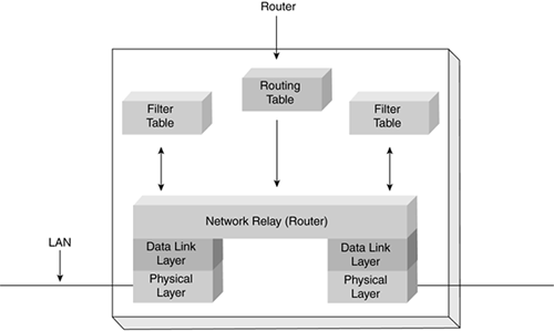
The routing and filter tables found in a router are similar to the tables used by bridges and switches. The difference between routing and switching tables is that instead of specifying link hardware (MAC) addresses, the router table specifies network addresses. The routing table lists known IP destination addresses with the appropriate network interface used to reach that destination. A default entry is used for all addresses not explicitly defined in the table, such as packets destined for the Internet. It's more manageable to have a single entry in the table for the Internet than to have an entry for each Internet site you might visit.


