VLAN Operation
Several issues are involved in the operation of a VLAN:
Who can participate in each VLAN
How VLANs communicate among each other
How devices within different VLANs can communicate with one another
VLAN Membership
There are three ways a network device can be assigned to a VLAN: by port, Layer 2 (MAC) address, or Layer 3 (network) address. The type of VLAN determines how a device is assigned. In a port-based VLAN, for example, you assign each switch port to a VLAN. In MAC address-based VLANs, membership is defined by the source or destination MAC address. VLANs based on Layer 3 information use the protocol type, such as the Internet Protocol (IP), and the Layer 3 (network) address in determining which VLAN the device is a member of.
Port-Based VLAN
In a port-based VLAN, such as that illustrated in Figure 8-5, each computer is assigned to its VLAN based on the port to which the computer is connected.
Figure 8-5. VLAN Membership Based on Switch Port Number
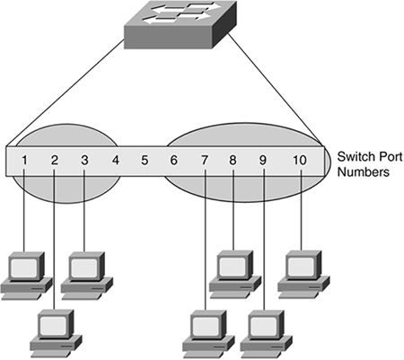
For example, ports 1 through 4 can be assigned to the sales VLAN, ports 6 through 10 to the engineering VLAN, and port 5 kept open as a spare port that you can assign to either VLAN. Or you can create a third VLAN with port 5 as a member. When a computer is connected to port 4, it becomes part of the sales VLAN. When that same computer is connected to port 6, however, it becomes part of the engineering VLAN.
note
On almost all switches today, all ports by default are part of VLAN 1. |
The main drawback of port-based VLANs is that you must reconfigure VLAN membership when a user moves from one port to another. If you are in an environment in which people are moving around all the time, port-based VLANs can become quite the headache.
Address-Based VLAN
In an address-based VLAN, such as that illustrated in Figure 8-6, each computer is assigned to its VLAN based on the Media Access Control (MAC) address of the computer.
Figure 8-6. Address-Based VLAN
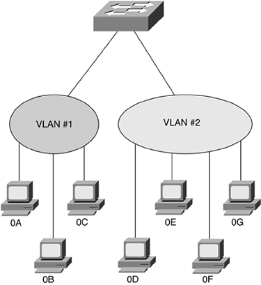
The computers with the MAC addresses 0A, 0B, and 0C are assigned to VLAN 1, and the computers with the MAC addresses 0D, 0E, 0F, and 0G are assigned to VLAN 2. (Note that these are not real MAC addresses.)
The main advantage of the address-based model is that the switch does not need to be reconfigured when a user moves to a different port, as illustrated in Figure 8-7.
Figure 8-7. Machine 0C Moved to New VLAN
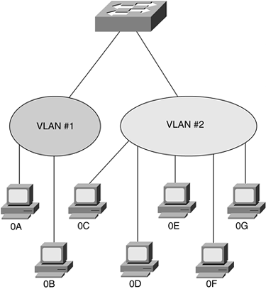
The user at machine 0C changed departments, and to support this move the network administrator removed the MAC address (0C) from VLAN 1 and assigned 0C to VLAN 2 without reconfiguring any switch ports. This type of change can happen about as quickly as you can type on a keyboard.
The primary issue with MAC address-based VLANs is that a single MAC address cannot be a member of multiple VLANs without special features available on the switch enabling the multiple VLAN membership.
Layer 3-Based VLAN
In a Layer 3-based VLAN, such as that illustrated in Figure 8-8, each computer is assigned to its VLAN based on the OSI model Layer 3, the network layer, and the address of the computer.
Figure 8-8. Layer 3-Based VLAN
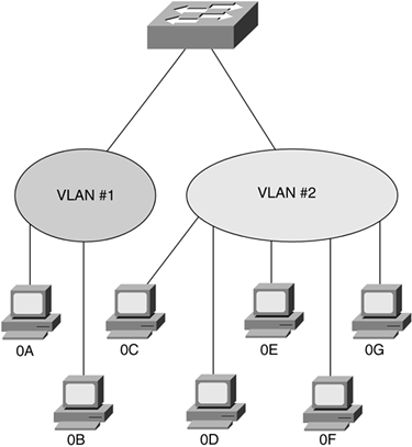
The primary benefit of using a Layer 3-based VLAN is that users can physically move their workstations to any network jack without the workstation's network address being reconfigured. This might make your life as a network manager much easier because you assign a network address, or range of addresses, to a VLAN only once, instead of having to reassign a MAC address to a new VLAN. The downside of Layer 3 VLANs is the slow performance caused by additional switch processing.
note
Because switches are Layer 2 devices, not Layer 3, additional processing cycles are needed for the switch to manage Layer 3-based VLANs. Even though you are using a Layer 3 address to differentiate, the device is being assigned to a Layer 2 broadcast domain (not forwarding the packet). |
Inter-VLAN Communication
We have discussed VLANs that are basically a special type of broadcast domain, in that a VLAN is defined by a switch port rather than by traditional physical boundaries, such as wiring hubs. Recall that when a host in one broadcast domain wants to communicate with another, a router must be involved, and the same holds true for VLANs.
For example, suppose that port 1 on a switch is part of VLAN 1, and port 2 part of VLAN 17, as illustrated in Figure 8-9.
Figure 8-9. VLAN 1 and VLAN 17
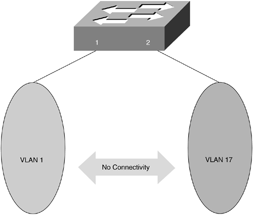
If all of the switch's ports were part of VLAN 1, the hosts connected to these ports could communicate with each other without issue. However, when the ports are made part of different VLANs, this communication is no longer possible. For a host connected to port 1 to communicate with another connected to port 2, a router must be involved, as illustrated in Figure 8-10.
Figure 8-10. VLAN 1 and VLAN 17 with a Router
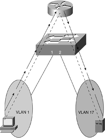
Traffic leaving the host in VLAN 1 passes through the switch to the router so that the traffic can be passed back through the switch to reach the host server in VLAN 17. Instead of using a router to enable this inter-VLAN communication, a Layer 3 switch might be used.
A Layer 3 switch is essentially a Layer 2 switch that can also act as a router, often through additional hardware and/or software features. If a switch is capable of Layer 3 functions, it can be configured to route traffic between VLANs defined within the switch, without the need for traffic to ever leave the switch for routing decisions. If a switch includes only Layer 2 functions, however, an external router must be configured to route traffic between the VLANs. In some cases, a packet can leave switch port 1, be forwarded to an external router, and then be routed right back to port 2 on the originating switch, as illustrated in Figure 8-10. For this reason, Layer 3 switches are popular to use throughout a corporate network.
Devices that are called Layer 3 switches track the Layer 3 addresses in and out of each port and build a table similar to a MAC address table for Layer 2. If they see the same address more than once, they forward the packet without looking at the routing table or sending it up to the main processor.
note
Regardless of the method chosen for inter-VLAN communication, either a router or Layer 3 switch, the most important point to remember is that when a host on one VLAN wants to communicate with a host on another, a routing (Layer 3) device must be involved.
Extending VLANs
To extend VLANs across different switches, a trunk link must be implemented, interconnecting the switches. This trunk link is often faster than the VLANs themselves. Think of a trunk link as being similar to an interstate highway; several small roads converge to one larger, and faster, road, as illustrated in Figure 8-11.
Figure 8-11. VLAN Trunks and Interstate Highways
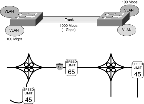
For example, you might interconnect two Gigabit Ethernet ports on different switches enabling the communication between the 100-Mbps VLANs on each switch. It is recommended that you use the fastest port available for trunk connections between switches, because this link often carries a great deal of traffic, most often for multiple VLANs.
Assume you have connected a link between the 100-Mbps ports of two switches, as illustrated in Figure 8-12.
Figure 8-12. 100-Mbps Link Between VLAN 1 Ports
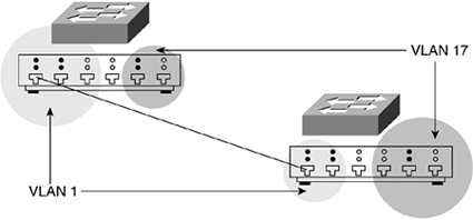
Note these ports are members of VLAN 1 on each switch. By default, without additional configuration, these ports act as a trunk link between these two switches; however, these ports pass traffic only for the VLAN associated with their port connections (in this case, VLAN 1). This type of link, in which traffic for only a single VLAN is passed, is referred to as an access link, as opposed to a trunk link, which carries traffic for multiple VLANs.
Access links get the job done in a single VLAN environment; however, multiple access links would be required if traffic from multiple VLANs were to be passed back and forth between switches. Having multiple access links between the same pair of switches would be a waste of switch ports. When traffic for multiple VLANs needs to be transferred across a single trunk link, VLAN tagging is used.
VLAN Tagging
When traffic from multiple VLANs travels across a link interconnecting two switches, you need to configure a VLAN tagging method on the ports that supply the link so that the receiving switch can identify the destination VLAN's traffic.
A number of tagging methods are in use for different technologies. The two discussed here are known as Inter-Switch Link (ISL) and 802.1q. ISL is a Cisco proprietary VLAN tagging method, whereas 802.1q is an open standard. This means that if you are connecting two Cisco switches, you could use ISL; if any non-Cisco switches are involved, however, 802.1q is your best option.
note
ISL is a Cisco proprietary VLAN tagging method; 802.1q is an open standard although both are similar in operation. |
ISL tags a frame as it leaves a switch with information about the VLAN to which the frame belongs. If a frame from VLAN 17 is leaving a switch, for example, the ISL port adds information to the frame header, designating that the frame is part of VLAN 17, as illustrated in Figure 8-13.
Figure 8-13. Frames Before and After Tagging by the Switch

When this ISL frame reaches the port at the other end of the switch, it looks at the ISL header, determines that the frame is meant for VLAN 17, strips off the ISL information, and forwards it into VLAN 17.
One of the issues with VLAN tagging is that by adding information to an Ethernet frame, the size of the frame can move beyond the Ethernet maximum of 1518 bytes to 1522 bytes. Because of this, all non-ISL ports see frames larger than 1518 bytes as giants, and therefore invalid. As shown in Figure 8-14, this is similar to putting a jumbo-sized hot dog in a regular-sized hot dog bun. Just because the hot dog is oversized doesn't make it a bad hot dog. ISL works in much the same way, although without the mustard and relish.
Figure 8-14. ISL Frames and Hot Dogs

Because the port might see the ISL frame as a giant, the port needs to be configured for ISL so that it can understand the different frame format.
After VLAN tagging has been configured on the ports associated with the link connecting switches, the link is known as a trunk link, as illustrated in Figure 8-15.
Figure 8-15. VLAN Tagging on a Trunk Link

A trunk link transfers frames from many different VLANs by using Cisco ISL or the standard IEEE 802.1q.


