VLAN Topology
VLANs can best be defined as a group of devices on either the same or different physical LAN segments, interacting with each if they are on the physical LAN segment.
Suppose, for instance, that you work in a two-floor office building and each floor has a LAN switch providing network connectivity to every computer on that floor. The first floor is supported by Switch 1, and the second floor is supported by Switch 2. On each floor of this building, there is also a marketing staff and an engineering staff. Because of office real estate, people are sitting wherever an open desk can be found.
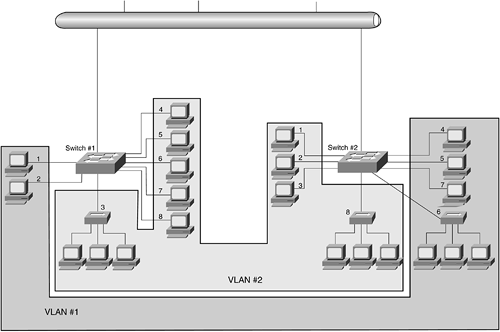
It is safe to say that the marketing and engineering departments have different jobs and therefore different network requirements. However, the fact that these two departments have different network requirements does not mean they cannot share the same network. Figure 8-4 illustrates how using VLANs provides virtual dedicated network resources to the marketing (VLAN 1) and engineering (VLAN 2) departments, while using the same physical network infrastructure.
Figure 8-4. VLAN 1 and VLAN 2

If we assign all the marketing staff on the first floor (Switch 1, ports 1 and 2) and all the marketing staff on the second floor (Switch 2, ports 4, 5, 6, and 7) to a single VLAN (VLAN 1), they can share resources and bandwidth as if they were connected to the same physical network segment. Similarly, if we assign all the first-floor engineering staff (Switch 1, ports 3, 4, 5, 6, 7, and 8) and the engineering staff on the second floor (Switch 2, ports 1, 2, 3, and 8), we create VLAN 2 for the engineering staff, providing the same illusion of physical connectivity provided to the marketing staff by VLAN 1.
It is important to remember that members of one VLAN cannot share the resources of any other VLAN without some sort of routing mechanism, such as a router or Layer 3 switch. For a member of the marketing staff in VLAN 1 to share resources with the engineering VLAN (VLAN 2), a router or a Layer 3 switch must be in place.
note
Communication between VLANs can occur only if there is a router or a Layer 3 switch in place enabling such connectivity. |
Switches with VLAN capability can create the same division of the network into separate LANs or broadcast domains and is similar to color coding your switch ports. In Figure 8-4, ports in the light gray area can communicate with other ports in the light gray area, and ports in the dark gray area can communicate with the other ports in the dark gray area.


