How to Configure Encryption
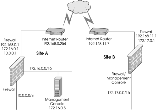
As you will find, the steps in configuring encryption are very similar regardless of which encryption scheme you use. Throughout this section, I refer to the proposed VPN setup in Figure 11.1.
Figure 11.1. Sample VPN configuration
NOTE!
As noted previously in the book, I treat 192.168.x.x as routable address space even though it is generally not considered routable per RFC1918. |
Planning Your Deployment
You need the following information when planning a VPN based in FireWall-1:
Which hosts and/or networks the remote site will be able to access through the VPN (your encryption domain)
Which hosts and/or networks will be accessible at the remote site (the partner's encryption domain)
Whether certificates or pre-shared secrets will be used
Site A has networks 10.0.0.0/8 and 172.16.0.0/16 behind its gateway. The encryption domain for Site A should include these networks along with any translated IP addresses for hosts on these networks. Likewise, Site B has the network 172.17.0.0/16 behind its gateway. The encryption domain for Site B should include these networks along with any translated IP addresses for hosts on this network.
Note that it may not be desirable for every host within the various networks to be accessible. This is okay. It is possible to restrict which hosts are accessible via the security policy. The encryption domain simply contains every network and host that could potentially be accessed through the VPN. The security policy determines which hosts can actually be accessed.
Should you use certificates or pre-shared secrets? The only time to consider using a pre-shared secret is when you are interoperating with either a pre-NG version of FireWall-1 or a third-party VPN. The version of FireWall-1 and how you define the VPN will determine which method(s) you can use. See the next subsection for details.
For certificates, the decision is very easy if the same management station manages all gateways in the VPN and they all run NG: Use certificates, which will be basically automatic. If a different management station manages one or more of the gateways, you will have to exchange CA keys so that your certificates can be validated. The current example demonstrates this.
Now that you know the necessary information about the different sides of the VPN, let's talk about how to set this up?in Traditional mode or Simplified mode.
Traditional Mode or Simplified Mode?
Traditional mode means defining VPNs the way it was always done in FireWall-1 4.1 and earlier versions, namely, with rules that use the action "encrypt." Simplified mode uses a VPN Community, which is similar to a group. It contains all the firewalls and encryption domains that will participate in a VPN. The community also defines which encryption methods will be used between the gateways, which simplifies configuration dramatically. A Simplified mode rulebase has a new column, If Via, which allows you to restrict certain types of traffic to be within the context of a VPN (e.g., site-a can talk to site-b only in an encrypted manner). This also makes for a far simpler rulebase, particularly when you get into a several-site VPN.
Simplified mode has an important limitation in FireWall-1 NG FP2 and before: You cannot set a pre-shared secret for IKE. If you are using NG FP2 and are setting up VPNs with non?Check Point endpoints (i.e., those endpoints represented as interoperable devices), you will need to use encryption rules.
You can determine whether new rulebases are created to use Simplified or Traditional mode by going into the Global Properties section, VPN-1 Pro frame, in SmartDashboard/Policy Editor, as shown in Figure 11.2.
Figure 11.2. Global Properties, VPN-1 Pro frame
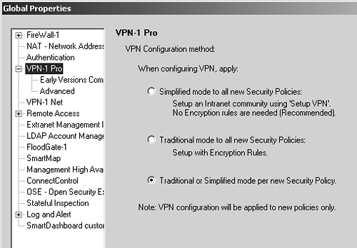
Until you have decided which method of creating a VPN is right for you, it is advisable to select the third option listed, Traditional or Simplified mode per new Security Policy. Once you have decided to go one way or the other, set the appropriate option.
NOTE!
This setting determines the mode only for newly created security policies. Old security policies maintain their existing Simplified or Traditional states when you change this setting in the VPN-1 Pro frame. |
It is possible to convert an existing Traditional mode rulebase into a Simplified mode policy using the conversion tool present in FireWall-1 NG FP3 and later within SmartDashboard/Policy Editor. However, you cannot convert from a Simplified configuration to a Traditional one. If you decide to convert back to encryption rules, you will need to remove all of your gateways from all VPN communities or your VPN will not function correctly.
I show how to set up the VPN using both Traditional and Simplified rules in this chapter. The next subsection explains how to configure the VPN in Traditional mode; the subsection after that covers Simplified mode configuration.
Configuring the VPN in Traditional Mode
You first need to define the encryption domain for Site A and Site B on both gateways. Site A's encryption domain includes:
10.0.0.0/255.0.0.0 (or 10.0.0.0/8)
172.16.0.0/255.255.0.0 (or 172.16.0.0/16)
Define network objects for both of these networks. Put them into a group called SiteA-encdomain. Similarly, for Site B, the encryption domain contains a network object for 172.17.0.0/255.255.0.0 (or 172.17.0.0/16), which needs to be created. Even though it is only one object, place it into a group called SiteB-encdomain. This makes it easier to expand later.
Once you have done this, you must configure Site A and Site B's local firewall workstation object so that they have the correct encryption domain. Edit the gateway object and select the Topology frame. Site A's gateway object is shown in Figure 11.3.
Figure 11.3. Gateway Properties, Topology frame for sitea-fw
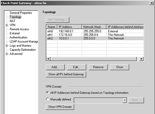
There are two options for the VPN domain: use topology or use a specific group that you have defined. If you follow recommendations made in Chapter 4 and create anti-spoofing and topology when you initially define the gateway objects, you can use topology, which is recommended. However, it is still advisable to create a group that encompasses your encryption domain. If you want your VPN domain to be something else, you can manually define it and assign it the appropriate group object.
Next, switch over to the VPN frame in the gateway object. Click on Traditional Mode Configuration. A dialog similar to Figure 11.4 appears.
Figure 11.4. Traditional mode IKE properties
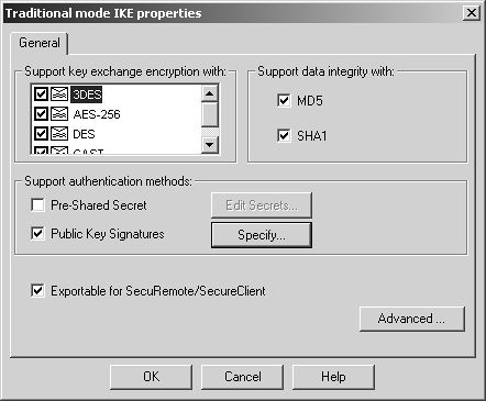
You can choose which key exchange and data integrity methods are supported by this gateway. In general, it is best to use the defaults for these properties, though a corporate security policy may dictate that some algorithms never be used. In that case, disable the appropriate methods. Note that the actual methods used will be determined by the encrypt rule used.
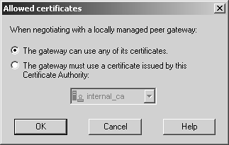
We'll use the Public Key Signatures option in our example VPN. If you click on the Specify button, a dialog similar to Figure 11.5 appears. Generally speaking, it is safe to leave this as the default shown in Figure 11.5. However, if you have multiple certificates generated by different CAs and want to force the gateway to use a specific one, you can do that here.
Figure 11.5. Allowed certificates for IKE
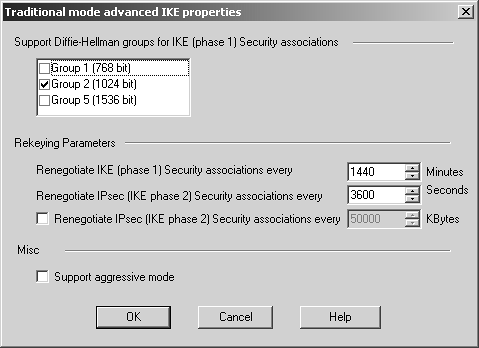
The advanced configuration options for IKE (see Figure 11.6), which you find by clicking on the Advanced button in the Traditional mode IKE properties dialog, are generally left as the defaults unless you are interoperating with a third-party VPN product. In these cases, you may need to change these advanced settings. If you are setting up a VPN with a third-party site, you should validate that these settings are identical to the ones used by the third-party VPN product.
Figure 11.6. Traditional mode advanced IKE properties
WARNING!
Under no circumstances should you enable aggressive mode. If you must enable aggressive mode to interoperate with a device, I strongly suggest upgrading the device or using a different device entirely. Aggressive mode uses a far less intense key exchange at the expense of some security. Security alerts were raised about this feature being enabled by default in FireWall-1 4.1 because it could be used to compromise the integrity of the VPN, particularly when pre-shared secrets are used. It's not a problem in FireWall-1 per se but rather a problem with the IKE specification itself. |
Now it is time to exchange certificate authority keys. Each site needs to export its CA key and send it to the other party. First, you must get to the ICA certificate. Either select Servers from the Manage menu in SmartDashboard/Policy Editor and double-click on internal_ca, or click on the Servers icon in the objects tree ![]() , expand Certificate Authority by clicking on it (if necessary), and double-click internal_ca. From here, select the Local Management Server tab and then click on the Save As button. Save the ICA to a file. Click on the View button to view the certificate details. The important things to note here are the MD5 and SHA-1 fingerprints. When Site B loads Site A's certificate (and vice versa), they should verify that the MD5 and SHA-1 fingerprints match, to ensure the certificate wasn't tampered with in transit.
, expand Certificate Authority by clicking on it (if necessary), and double-click internal_ca. From here, select the Local Management Server tab and then click on the Save As button. Save the ICA to a file. Click on the View button to view the certificate details. The important things to note here are the MD5 and SHA-1 fingerprints. When Site B loads Site A's certificate (and vice versa), they should verify that the MD5 and SHA-1 fingerprints match, to ensure the certificate wasn't tampered with in transit.
After exchanging certificates, it is time to import the other site's CA key. The following example shows Site B's CA key being imported into Site A's management station. Site A also needs to import Site B's CA key using a similar procedure.
You need to create a new CA object. You can do this by selecting Servers from the Manage menu in SmartDashboard/Policy Editor, clicking the New button, and selecting Certificate Authority. Alternatively, you can click on the Servers icon in the objects tree, right-click on Certificate Authority, and select New. Either way, you see a dialog similar to Figure 11.7.
Figure 11.7. Certificate Authority Properties, General tab for siteb-ca
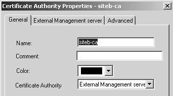
Set the Certificate Authority type to "External Management server" and click on the corresponding tab to see a dialog similar to Figure 11.8.
Figure 11.8. Certificate Authority Properties, External Management server tab for siteb-ca
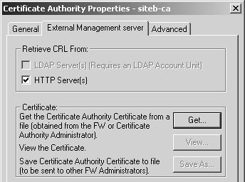
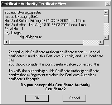
Click on the Get button and locate the certificate file for Site A's CA. Once you have selected the file, a dialog similar to Figure 11.9 will appear. Scroll down in this window and verify that the MD5 and SHA-1 fingerprints match what Site A has for its CA key. Click OK.
Figure 11.9. Certificate Authority Certificate View
Now that the CA keys are correctly imported, Site B's gateway can be created on Site A's management station and vice versa. In the objects tree, select the Network Objects icon, then right-click on Check Point and select New Check Point, followed by Externally Managed Gateway. Or you may select Objects from the Manage menu, click on New, select Check Point, and then select Externally Managed Gateway. You can then create the object for the remote gateway. Figure 11.10 shows Site B's gateway object on Site A's management station.
Figure 11.10. Gateway Properties, General Properties frame for siteb-fw
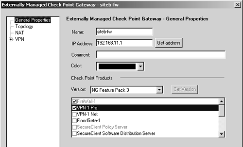
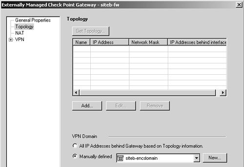
Figure 11.11 shows the Topology frame, where you manually choose the encryption domain to be the group siteb-encdomain, a group object created earlier.
Figure 11.11. Gateway Properties, Topology frame for siteb-fw
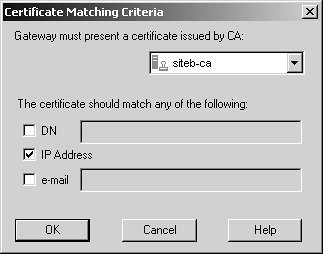
Finally, you need to configure the VPN properties, specifically to require that Site B's certificate be from Site B's certificate authority. Go to the VPN frame, click on Traditional Mode Configuration, then click on Matching Criteria. Figure 11.12 shows the options you should select for this example.
Figure 11.12. Certificate Matching Criteria for siteb-fw
In general, the certificate matching criteria options are those listed below.
Gateway must present a certificate issued by CA: This gateway must present a certificate from the specified CA for VPN-related operations. CA objects and LDAP account units can be listed in the options.
The certificate should match any of the following: The certificate must contain one of the checked options. DN (for the distinguished name) usually refers to "CN=fully-qualified-domain-name." IP Address means the certificate must include the gateway's IP address as defined in the general properties. Some certificates are also generated with an e-mail address.
NOTE!
It is not necessary to go into the Traditional mode configuration on Site B's firewall object because certificates are enabled by default. |
Once Site B has configured Site A's gateway object in a similar manner as described previously, you can create rules similar to those shown in Figure 11.13.
Figure 11.13. Encryption rules

Note that there are two rules listed: one to permit the traffic from Site A to Site B and one to permit the traffic from Site B to Site A. Although you can certainly combine the two rules into one, I do it this way to suppress the error message "Encryption Failed: gateway connected to both endpoints," which occurs when you use two rules instead of one. The two rules permit everything between the encryption domains. You can make these rules more restrictive by adding a specific service, specific hosts, or both, or you can even eliminate one of the rules to restrict this to a one-way VPN. Nothing says you have to allow access to all hosts in the encryption domain; I just do it here for simplicity.
Now to configure the encryption action. Right-click on both Encrypt actions in the rulebase, then click on Edit Properties. Select IKE and click on Edit. A screen similar to Figure 11.14 appears.
Figure 11.14. IKE Phase 2 Properties for encryption
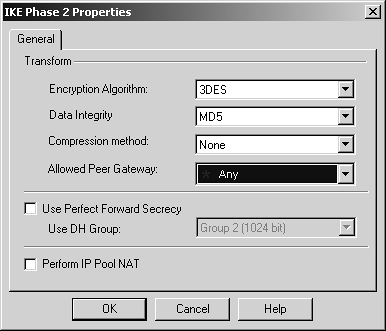
The options you can specify here include the following.
Encryption Algorithm: This specifies what algorithm will be used to encrypt the data. In most cases, you should use AES-128 or AES-256. If you have a cryptographic accelerator, use 3DES because, as of January 2003, none of the cryptographic accelerator cards support AES.
Data Integrity: The default here is MD5, but SHA-1 is usually a better choice. However, on the performance tests I've seen on Nokia IP Security Platforms, MD5 performs a little better.
Compression method: If you wish to compress the VPN data stream, it is enabled here. Deflate is the only option you can choose.
Allowed Peer Gateway: You can specify which gateways are allowed for this rule.
Use Perfect Forward Secrecy: This option ensures that an eavesdropper who uncovers a long-term encryption key cannot use it to decrypt past captured traffic. It is highly recommended that you enable this option; it is disabled by default.
Perform IP Pool NAT: If enabled, VPN connections bound for the local gateway will be subject to IP Pool NAT. The specific pool of addresses that will be used is defined in the local gateway object under the NAT frame. The configuration for IP Pool NAT is described in Chapter 12 in the High-Availability and Multiple Entry Point Configurations section.
NOTE!
Ensure that the properties specified in the encryption action match in all encrypt rules between the two parties. |
Now that you've defined everything, it's time to install the security policy and test the VPN by trying to communicate through it.
Configuring the VPN in Simplified Mode
As in Traditional mode, you must configure the local topology of a VPN in Simplified mode so that it actually contains the encryption domain. This means creating the networks and adding them to sitea-encdomain and siteb-encdomain. You will also need to import the remote site's CA key and configure the remote gateway's matching criteria so that it will allow only certificates signed by the remote site's CA key. Since the steps are identical to the previous example, at least up to the point of creating actual rules, they are not repeated here.
After creating the gateways and setting the encryption domains, you need to create a VPN Community. There are two types of VPN Communities: Meshed Communities and Star Communities. In a Meshed Community, all participating gateways can talk to each other. In a Star Community, you can specify two types of gateways: central gateways and satellite gateways. Central gateways all talk to one another as they do in a Meshed Community. Satellite gateways can talk only to the central gateways, not other satellite gateways. However, with VPN Routing in FireWall-1 NG FP3 and later, satellites can talk to each other via a central gateway. See FAQ 11.7 later in this chapter for details on how to implement this.
NOTE!
FireWall-1 NG FP1 allows only a single VPN Community to be used. |
Click on this icon ![]() in the objects tree, right-click on Site-to-Site, and select New, then Meshed. Alternatively, select VPN Communities from the Manage menu, click on New, and select Site-to-Site, then Meshed. Either way, you see a screen similar to Figure 11.15.
in the objects tree, right-click on Site-to-Site, and select New, then Meshed. Alternatively, select VPN Communities from the Manage menu, click on New, and select Site-to-Site, then Meshed. Either way, you see a screen similar to Figure 11.15.
Figure 11.15. Meshed Community Properties, General frame
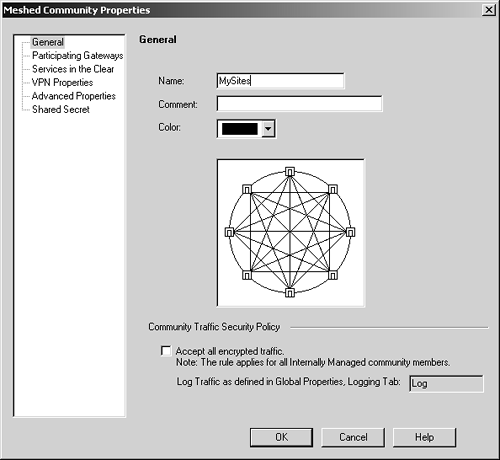
The options available in this frame are listed below.
Name: Enter the name you wish to give to the VPN Community.
Comment: In this field you can further describe the VPN Community.
Color: Choose an appropriate color for your VPN Community.
Accept all encrypted traffic: This property is present in NG FP3 and later. If this property is enabled, it will not be necessary to create an explicit rule to allow traffic between members of the community. All traffic is logged by default, though this can be changed in the Global Properties section, Log and Alert frame.
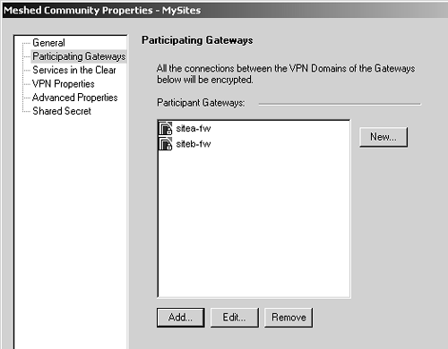
Figure 11.16 shows the Participating Gateways frame, where you can specify which gateways are part of the VPN Community. From this screen, you can add gateways, select gateways and edit them, remove gateways from the community, and create new gateway objects. The gateways for both Site A and Site B need to be added to the VPN Community.
Figure 11.16. Meshed Community Properties, Participating Gateways frame
As of NG FP3, VPN Communities may also allow "services in the clear," which means that the specified services will not be encrypted through the VPN Community. This may be useful for troubleshooting purpose (i.e., permitting ICMP through the VPN Community) or for services that are already encrypted (e.g., SSH, https). However, you cannot add services of type INSPECT to these groups.
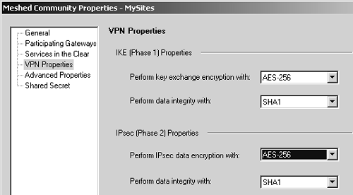
In the VPN Properties frame, shown in Figure 11.17, you specify the encryption properties that will be used for all members of the VPN Community.
Figure 11.17. Meshed Community Properties, VPN Properties frame
In the Advanced Properties frame, shown in Figure 11.18, you can specify additional properties. A new property in NG FP3 and later is the "Disable NAT inside the VPN community" property, which means that you do not have to explicitly define rules that disable address translation as was necessary with Traditional mode.
Figure 11.18. Meshed Community Properties, Advanced Properties frame
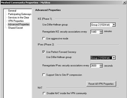
The nice thing is that these properties have to be configured in only one place?the VPN Community. This is somewhat simpler than the Traditional mode method, which required configuring each individual gateway with the correct options.
FireWall-1 NG FP3 and later also allow you to include non?Check Point devices as part of a VPN Community by allowing IKE pre-shared secrets for all externally managed VPN gateways. This is because not all third-party devices support certificate-based authentication, or at least a type that is compatible with FireWall-1. In NG FP2 and prior, if you had to establish a VPN with a device on which you could not perform certificate-based authentication, you had to use Traditional mode. You can define these secrets in the Shared Secret frame of the Meshed Community Properties section.
Figure 11.19 shows how the rulebase looks. As stated previously, you can easily restrict this by service or source/destination if you want. I am doing it the "easy" way for simplicity.
Figure 11.19. Simplified VPN rulebase configuration

One particularly attractive thing about this configuration: As the number of sites in the VPN Community grows, the rulebase doesn't change unless it is necessary to limit access through the VPN by source, destination, or service. In the simplest configuration (allow everything), you can use exactly the same rule and it doesn't have to change at all!
Gateway Clusters for High-Availability VPNs
Gateway clusters allow for High-Availability (HA) VPNs, which, along with FireWall-1's State Synchronization mechanism, allow for a secondary gateway to be able to process encrypted traffic in the event the primary firewall fails. The gateway cluster object can be used only if an underlying HA solution is present. This could be Stonesoft's Stonebeat Full Cluster, IPSO's VRRP or Clustering, Rainfinity's Rainwall, or Check Point's own HA Module. You also need to have your management console on a separate platform from the systems that you intend to configure into a gateway cluster.
A gateway cluster is nothing more than a virtual firewall. It takes two or more firewalls in an HA configuration and makes them appear as a single entity for the purposes of installing a security policy and encryption. The mechanics of establishing a gateway cluster are described in Chapter 13.
Setting up a VPN involving gateway clusters is not very different from setting up a VPN involving a single gateway. The moment you make a firewall workstation object part of a gateway cluster, many of the tabs in the workstation properties simply disappear. This configuration needs to be done from the gateway cluster object. When you configure the VPN-related parameters for the firewall, you configure them on the gateway cluster object, not on the workstation object for the firewalls that are members of the gateway cluster.
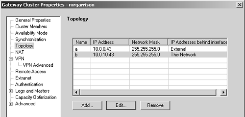
When you are defining the remote end of the VPN and it uses a gateway cluster, you simply treat it as if it were a single firewall object. You can simply refer to a remote gateway cluster with a single workstation object. However, you need to define the Interfaces tab. Include all of the IP addresses on all gateways in the gateway cluster, including the gateway cluster IP address, similar to Figure 11.20. The interfaces' names and the netmasks are not important because you are not using this as a basis for enforcing anti-spoofing. What is important is that you enter all of the IP addresses.
Figure 11.20. Entering interface IP addresses for a gateway cluster object
WARNING!
Despite Figure 11.20 showing you to enter the interface names in a gateway cluster object, entering anything into the Interfaces tab on a gateway cluster object may cause problems in some NG FP3 configurations. See FAQ 11.6 for details. In NG AI, you should use the actual interface names. |
Due to how gateway clusters work, some interoperability issues arise with gateway clusters and third-party VPN products. These issues, along with solutions, are documented in the next section.


