Sample Configurations
The three situations presented here are representative of situations I have encountered in the real world. Each is designed to demonstrate what people typically do with SecuRemote and SecureClient and how the situations are implemented on the chosen platform.
Creating a Simple Client-to-Site VPN
The Situation
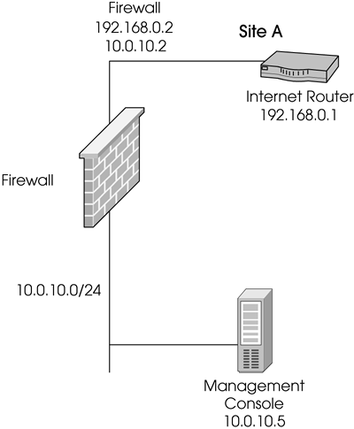
You are the firewall administrator for a company that has one site and employs several telecommuters. The clients need to be able to fully access the internal network. The clients also require protection, so SecureClient will be used. Hybrid IKE will be used to authenticate the users. A Traditional mode security policy exists for outgoing traffic (listed in the Goals subsection). The management console and the firewall are on separate hosts (see Figure 12.46).
Figure 12.46. Sample client-to-site VPN network map
The Goals
Allow SecuRemote clients to access all hosts on the internal network with any service.
Internal hosts are allowed to access sites on the Internet via FTP, HTTP, or HTTPS.
SMTP can originate from predefined SMTP servers inside the network to the Internet. (They are in a group called SMTP-Servers.)
SMTP can go to the external SMTP server from anywhere (external-smtp-server is already defined).
SecureClient hosts are allowed to access both the Internet and the encryption domain.
Only hosts in the encryption domain are allowed to access SecureClient hosts, no others.
Deny all other traffic.
The Checklist
Define the necessary users, put them into a group (if necessary), and install the user database.
Define the encryption domains for the local site.
Configure the firewall workstation objects for the correct encryption domain.
Create the necessary encryption rules.
Configure the rule to permit the FW1_Topo service to the management console.
Configure the Desktop Security policy to permit outbound access to the Internet and the encryption domain.
Configure the Desktop Security policy to allow encrypted access from the encryption domain to the SecureClient host, denying all other traffic.
Install the security policy.
The Implementation
Ensure that your gateway object has the Policy Server package loaded and enabled. The gateway object should also have the SecureClient Policy Server option checked in the General Properties frame.
For this example, let's use the names beavis, butthead, stewart, and daria. Create these users and place them into a group called telecommuters. (See Chapter 8 for explanations of how to create users and groups.)
Hybrid Authentication will be used. This means each user's existing password as defined in the definition in the Password section will apply.
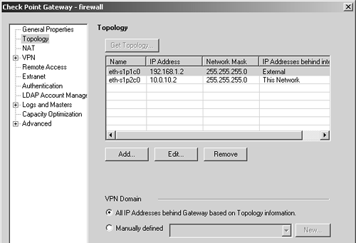
Next, you need to define the encryption domain. Generally speaking, if your topology is set up correctly and contains anti-spoofing, similar to what is shown in Figure 12.47, you need not explicitly define the encryption domain, though manually defining it makes it somewhat easier to use in a rulebase. To manually define the encryption domain, create the appropriate network object(s), add them to a group, and then set the encryption domain for that group.
Figure 12.47. Gateway Object, Topology frame
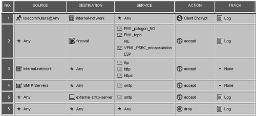
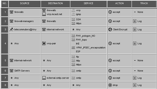
Your rulebase needs to look like the one shown in Figure 12.48. Rule 1 permits the telecommuters to access the internal network via SecuRemote. Rule 2 permits SecuRemote users to fetch the network topology, log into the Policy Server, and establish an encrypted session with the firewall. Without this rule, users cannot establish the site in the SecuRemote client. Rules 3 through 6 are necessary to establish the security policy defined in the Goals subsection above.
Figure 12.48. Sample rulebase
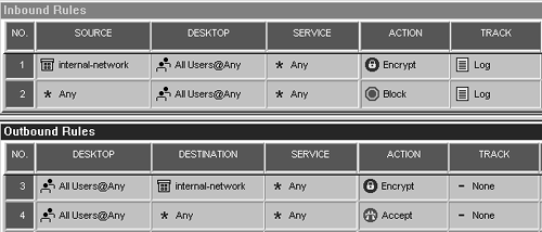
Because you also need to protect your SecureClient users, you need to create a Desktop Security policy. If you did not initially create a policy with a Desktop Security component, select New from the File menu, select the "Add policy to an existing package" option, and check the Desktop Security box.
Figure 12.49 shows how the final security policy looks. Install the security policy and test it.
Figure 12.49. Sample Desktop Security policy
Notes
This is a somewhat simplified example. Most sites have far more complex security policies. Just make sure your VPN rules are listed before any rules that allow outbound traffic to the Internet, that you have the necessary rules to permit IKE, and that the topology requests are listed before any firewall Stealth rules.
Using SecureClient with Gateway Clusters
The Situation
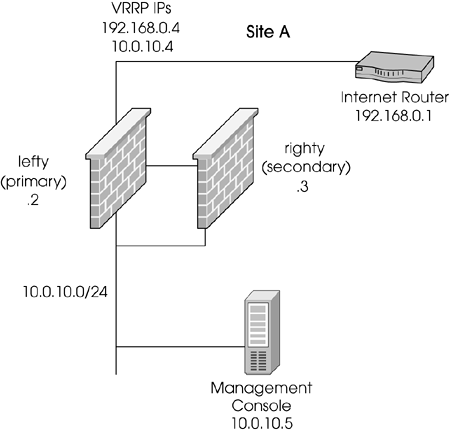
The previous firewall has been replaced with a pair of Nokia IP530s in an HA configuration using VRRP Monitored Circuits (see Figure 12.50). All other aspects of the network and the security policy are the same. Additional traffic must be permitted to the firewalls for management purposes. In addition, the company has decided to implement Office Mode.
Figure 12.50. Sample configuration with VRRP pair
The Goals
Maintain the security policy as much as possible (from the previous configuration).
Add rules to permit VRRP, if necessary.
Add rules to permit specific management clients the ability to use the SSH and HTTPS services to the firewalls to perform management functions.
The Checklist
Define the gateway objects for each firewall.
Define the gateway cluster object.
Add the individual gateway objects to the gateway cluster object.
Configure the gateway cluster object to use encryption.
Configure the rulebase to allow the client management stations access to the firewalls.
Install the security policy.
SecureClient users must update the site definition.
The Implementation
First you need to create a gateway object for each firewall. Make sure the Interfaces tab for each gateway object has all of the physical interfaces properly defined. Next, create the gateway cluster object. In the General Properties frame, specify the VRRP IP address used in your Monitored Circuit configuration (use the external IP, of course). Define the synchronization network in the Synchronization frame.
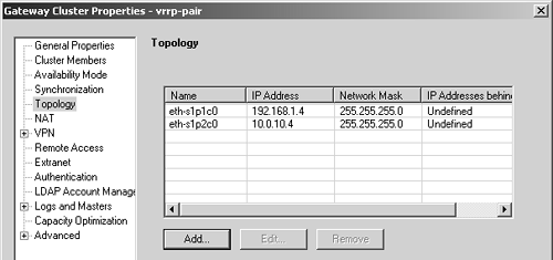
The next step depends on which version of FireWall-1 you're using. In NG FP2, each VRRP IP address needs to be included in the Topology frame for the gateway objects that make up the gateway cluster. The interface names for these IPs is not important. In NG FP1, FP3, and above, define the VRRP IPs in the Topology frame using the corresponding physical interface names. Figure 12.51 shows this configuration.
Figure 12.51. Gateway Cluster Properties, Topology frame
Go to the VPN frame and click on the Traditional Mode Configuration button. Ensure that Exportable for SecuRemote/SecureClient is checked.
The next step is to configure the rulebase for VRRP. VRRP is a predefined service in NG (IP protocol 112). The rulebase and/or anti-spoofing must allow for the following actions.
VRRP packets can originate from either firewall.
VRRP packets can go to the VRRP Multicast Address (vrrp.mcast.net, 224.0.0.18) on any interface where VRRP is configured.
VRRP packets can also go to a specific firewall interface for a triggered VRRP update.
Each firewall must be allowed to originate IGMP traffic in order to join a multicast group. This is necessary on switches.
However, due to a bug in NG FP1 and NG FP2, FireWall-1 interprets VRRP packets as coming from the VRRP IP itself. This means you must also create host objects for each VRRP IP address. Put them into a group called firewalls. In addition, you need to create vrrp.mcast.net, which is a host object with the IP address 224.0.0.18 (as mentioned above).
Next, create the rules to allow the workstations that manage the firewalls to access the firewalls via SSH and HTTPS. Create a group, add the various workstation objects to this group, and then use this group in a rule.
Other than these two rules, along with changing the rule permitting certain VPN traffic to the firewall so that it references the gateway cluster object, the rulebase shown in Figure 12.52 looks basically the same as it did in the previous configuration.
Figure 12.52. Sample rulebase with gateway cluster
Once you install the security policy, users will have to update their sites to take full advantage of the Gateway Cluster configuration. The client's userc.C file will, after a site update, contain the IP addresses of the real firewalls and the virtual firewall's IP address.
Notes
This is an overly simplistic configuration, but it demonstrates how to use the Gateway Clusters feature. It also shows that, once implemented, the configuration does not change all that much.
In NG FP2 and before, you cannot use the gateway cluster object as part of a rule. In Rule 4, you would use a host object of the same IP as the external IP of the firewall instead.
IPSO 3.6 does not require a VRRP rule because this version of IPSO sends certain VRRP packets directly past FireWall-1. Refer to Resolution 14946 for details.
Configuring Multiple Entry Point SecureClient
The Situation
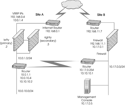
The network used in the previous sample configurations has been merged into a larger network via a WAN link. Other parts of this WAN have their own Internet access protected by Check Point FireWall-1. It is desirable to use these other connections and firewalls as backup gateways for SecuRemote users. Because of this configuration, Office Mode will be used. Each firewall needs to be allocated a unique, nonroutable subnet so that incoming SecuRemote clients can be assigned an IP that routes to the specific firewall they enter. Also, the original site needs to be reorganized somewhat to account for the WAN link. A WAN router has been added between the Nokia IP440s and the internal network with a new subnet. This is to keep the routing configuration a bit simpler.
Note that most of your attention should be focused on the original site (Site A in Figure 12.53). I will discuss the changes that need to occur on Site B (they are similar) but will leave the actual steps as an exercise.
Figure 12.53. A Multiple Entry Point configuration with gateway clusters
The Goal
Maintain the security policy as much as possible (from the previous configuration).
The Checklist
Modify the encryption domains on all firewalls to include the same set of network objects, including all the firewalls.
Configure the rulebase properties to enable backup gateways for SecuRemote clients and IP Pool NAT logging options.
Choose appropriate address ranges for each gateway to use for IP Pool NAT.
Configure each workstation and/or gateway cluster object so that the other firewalls are backup gateways.
Configure each local gateway's workstation or gateway cluster object so that NAT is performed for SecuRemote connections.
Install the security policy.
The Implementation
The other site (Site B in Figure 12.53) has an encryption domain of 10.17.0.0/16. Both sites need to have an encryption domain that contains the following:
All three firewalls at both sites
10.0.10.0/24
10.0.1.0/24
10.17.0.0/24
Create a group containing all of these objects. Edit the vrrp-pair object. In the Topology frame, specify the VPN domain as this group. A similar change will be made on maingw, the object for the firewall at Site B. In the VPN frame in the vrrp-pair object, check Enable Backup Gateways and specify maingw as your backup gateway. The analogous change should not be made on maingw.
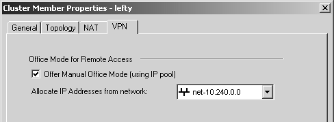
Now go to the Cluster Members frame. Edit each member of the gateway cluster. Go to the VPN tab and set the Office Mode pool to the same network on both members of the cluster (see Figure 12.54).
Figure 12.54. Cluster Member Properties, VPN tab
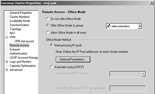
After editing the cluster members, go to the Remote Access frame in the vrrp-pair object. Enable Office Mode for the telecommuters group and set the Office Mode method to Manual as shown in Figure 12.55.
Figure 12.55. Gateway Cluster Properties, Remote Access frame
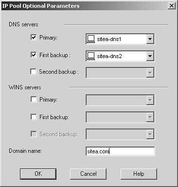
Click on the Optional Parameters button and specify the DNS information as shown in Figure 12.56.
Figure 12.56. Optional Parameters for Office Mode
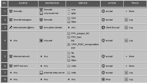
To accommodate the new encryption domain, you have to change Rule 3 in your rulebase so that the rule includes encryption-domain instead of internal-network (see Figure 12.57). Other than that, the rulebase is identical to the one in the previous configuration.
Figure 12.57. Rulebase for Multiple Entry Point Configuration
Notes
Despite the fact that gateway clusters are being used, a failover of the primary firewall will cause any active connections to terminate. If both members of the cluster fail, only then will the backup gateway be used.


