Introducing Rapid Spanning Tree Protocol
The primary focus thus far has been on legacy STP as defined by IEEE 802.1D. As you have learned in the previous sections, the immediate hindrance of STP is convergence. It takes anywhere from 30 to 50 seconds depending on the type of failure to converge the network. RSTP helps with convergence issues that plague legacy STP. RSTP has additional features similar to UplinkFast and BackboneFast that offer better recovery at Layer 2 than STP.
RSTP is based on IEEE 802.1w standard. Numerous glaring differences exist between RSTP and STP. For starters, RSTP requires full-duplex point-to-point connection between adjacent switches. Half duplex, generally speaking, denotes a shared medium whereby multiple hosts share the same wire; a point-to-point connection cannot reside in this environment. As a result, RSTP cannot work in a half-duplex mode. STP and RSTP also have port designation differences. RSTP has Alternate and Backup port designation, which are absent from the STP environment. Ports not participating in spanning tree are known as edge ports. Edge ports should be configured using the set spantree portfast command. The edge port becomes a non-edge port immediately if a BPDU is heard on the port. Non-edge ports participate in the spanning-tree algorithm; hence, only non-edge ports generate Topology Changes (TCs) on the network when transitioning to forwarding state only. TCs are not generated for any other RSTP states. In legacy STP, TCNs were generated for any active port that was not configured for portfast.
RSTP port designations include the following:
Root Port (RP)? Defined as port closest metrically to the Root. This designation is also seen in legacy STP.
Alternate Port? Alternate path to get to the Root. Alternate ports do not forward traffic. An alternate port is equivalent to a backup of the RP.
Designated Port (DP)? Port used to forward the best BPDU on each segment.
Backup Port? This port is a backup to the DP on the segment. It does not forward traffic.
These port designations are illustrated in Figure 10-8.
Figure 10-8. RSTP Port Designations
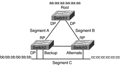
All ports on the Root that are participating in spanning tree will be forwarding on each of the segments. Hence, Root will forward its BPDUs to both Switch2 and Switch3. Switch2 and Switch3 RPs are directly connected to the Root. The RPs will be receiving configuration BPDUs from the Root and will be in forwarding state. Switch2 and Switch3 will be competing as to which switch will forward BPDUs on Segment C. The decision process is the same for both RSTP and STP. As noted in Chapter 1, the decision process involves the following:
Lowest path cost to the Root
Lowest Sender Bridge ID (BID)
Lowest Port ID
In Figure 10-8, the lowest BID will determine which switch will be the DP for Segment C because the cost to the Root is the same for both Switch2 and Switch3. The BID is composed of bridge priority and MAC address. The default priority value is the same for both Switch2 and Switch3; therefore, the decision is going to be based on the lowest MAC address. Switch2 has a lower MAC address than Switch3, and, as a result, will be forwarding on Segment C. As noted in Figure 10-8, the DP is associated with Switch2. The Backup Port on Switch2 will be discarding. It will be backing up DP should it go down. The Alternate Port is in discarding state and will be backing up the RP on Switch3. The only forwarding port on Segment C will be the DP on Switch2.
RSTP States
Table 10-1 shows the different port states between RSTP and legacy STP. The three port states in RSTP are the following:
Discarding
Learning
Forwarding
Operational Port State | STP Port State | RSTP Port State |
|---|---|---|
Enabled | Blocking | Discarding |
Enabled | Listening | Discarding |
Enabled | Learning | Learning |
Enabled | Forwarding | Forwarding |
Disabled | Discarding | Discarding |
In Cisco implementation, discarding is replaced with blocking.
RSTP BPDU
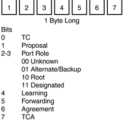
The BPDU packet has also changed with RSTP. (See Figure 10-9.) The version field in legacy STP was set at 1, but in RSTP, the version is set at 2. The motivation here is for RSTP to be able to communicate with legacy STP. The Flag field in the STP BPDU packet contained TCN and TCA. In RSTP, the Flag field, 1 byte long, has been modified to accommodate port designations and proposal/agreement between adjacent switches. BPDUs are sent every 2 seconds. Unlike in legacy STP, in RSTP, each switch generates its own BPDUs regardless if it hears BPDUs from the Root. In legacy STP, BPDUs were only generated by the Root and propagated throughout the spanning-tree domain. As a result, when a switch did not receive a configuration BPDU, it did not know where the failure occurred. In RSTP mode, the switch needs only to worry about its immediate neighbors. Hence, BPDUs also serve as keepalive mechanisms between adjacent switches. If the switch does not hear three consecutive BPDUs from its downstream neighbor, it will transition appropriate ports to converge the network.
Figure 10-9. RSTP BPDU Flag Field
RSTP Proposal/Agreement
Figure 10-10 depicts adjacent switches participating in RSTP implementation. RSTP switches require BPDUs from their connected neighbors to keep the link up. This mechanism is outlined in the RSTP proposal/agreement process.
Figure 10-10. RSTP Proposal/Agreement
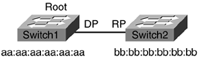
The mechanism involved in proposal/agreement between adjacent switches is very fast. It takes less than few seconds to transition a port to the appropriate state, whereas in STP, it took a minimum of 30 seconds. In Figure 10-10, BPDU exchange between Switch1 and Switch2 has not yet taken place. Only in discarding and learning states will proposal BPDUs be sent. Assume that the ports connecting the two switches are in learning state: Switch1, with lower BID, sends a proposal BPDU to Switch2. Switch2 having received the proposal sees that Switch1 has better BPDU; it will accept Switch1 as the Root for the VLAN. Switch2 will send an agreement BPDU back to Switch1. In a situation where Switch1 does not receive an agreement BPDU, it will fall back to legacy STP mode.
A new connection has been set up between Switch1 and Switch3. (See Figure 10-11.) When this connection comes up, Switch3 will receive a better BPDU from Switch1. It must, therefore, transition its current RP and designate a new RP.
Figure 10-11. A New Connection Between Switches
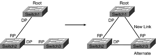
The following steps outline how Switch3 chooses a new RP:
- Step 1. A new connection between Switch1 and Switch3 has been set up.
- Step 2. Switch3 receives a better BPDU from Switch1. It keeps the new port in blocking state.
- Step 3. Switch3 transitions the current RP to Alternate port (discarding state).
- Step 4. Switch3 sends an agreement BPDU to Switch1.
- Step 5. Switch3 transitions the new RP to forwarding state.
- Step 6. Switch1 receives the agreement BPDU and transitions its port to forwarding state as well.
RSTP Legacy Support
RSTP is backward compatible with legacy STP. Typically, RSTP generates BPDUs every 2 seconds on the wire informing the segment of which bridge is the Root. Based on this information, the downstream bridges will appropriately designate their spanning-tree ports. The problem is that legacy STP devices do not understand these BPDU messages that they are receiving from RSTP-enabled devices. As a result, legacy STP devices will continue to generate their own BPDUs and ignore the RSTP BPDUs. Legacy STP BPDUs may have wrong information as to which bridge is the Root in the network. It becomes crucial for RSTP implementation to be backward compatible to prevent such a scenario.
The RSTP device is engineered so that it can deal with legacy STP devices on the same Layer 2 network. RSTP handles the legacy STP device problem through a timer. The RSTP device will wait 4 seconds (2 * hello interval) to see if legacy STP BPDUs will cease. If they do not, RSTP will fall back to legacy STP mode. Now, all the bridges will communicate via legacy STP specifications. Hence, the fast convergence and relative stability gained through RSTP is lost. Manual intervention is required to revert back to RSTP mode. Unfortunately, no mechanism is in place today to allow an RSTP device to revert back to RSTP mode if the legacy STP device disappears.
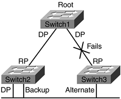
RSTP Direct Failure
RSTP has natively implemented the same type of mechanisms involved in UplinkFast and BackboneFast. In Figure 10-12, when Switch3 loses its RP, it immediately transitions the Alternate port into forwarding mode. In legacy STP mode, a direct failure of this type would have taken 30 seconds. Unlike the UplinkFast mechanism, the RSTP mechanism does not use dummy multicast generation to flush the CAM entries. TCs generated by RSTP to the upstream switch clear the appropriate CAM entries associated with the broken link.
Figure 10-12. RSTP Convergence Due to Link Failure
When a TC bit is set, the switch starts a TC While timer equal to 4 seconds (2 * hello interval) for all its non-edge ports. It flushes the MAC addresses that were associated with that port. The upstream switch that received the TC BPDU will flush its MAC addresses from all ports except the port that received the BPDU. This process streamlines the convergence process. In legacy STP, the TCNs first needed to be propagated to the Root, which afterward generated configuration BPDUs that were propagated back to the spanning-tree domain. The amount of time it took to converge the network was contingent upon how big the spanning-tree domain was. In RSTP, the TCs are flooded quickly to non-edge ports and RPs, and the upstream switches flush their CAM entries, resulting in faster convergence time. The downside to this process is some flooding does take place in the network.
RSTP Indirect Failure
Referencing back, Figure 10-6 shows an indirect type of failure that would take 50 seconds for spanning tree to converge. Using BackboneFast, the convergence time is reduced to 30 seconds. Maxage timer does not exist in RSTP. RSTP takes an active role in bringing the network into convergence rather than passively waiting for timers to expire before transitioning a non-edge port.
The following steps outline how RSTP handles indirect link failures:
- Step 1. Switch3 loses its RP connection to the Root. As a result, Switch3 starts to generate BPDUs, informing other switches that it is the Root.
- Step 2. Switch2 receives the inferior BPDUs from Switch3. Switch2 knows through periodic BPDUs that it still has a connection to the Root.
- Step 3. Switch2 sends BPDUs informing Switch3 that Switch1 is still the Root.
- Step 4. Upon receiving the superior BPDUs, Switch3 stops sending BPDUs. It transitions its DP to RP.
Configuring RSTP
RSTP is also known as Per VLAN Rapid Spanning Tree Plus (PVRST+). It requires, at minimum, Catalyst OS Release 7.5(1). RSTP simply requires one command to be enabled. The spantree mode command globally enables RSTP for the switch. (See Example 10-14.) The command needs to be performed on all switches in the Layer 2 network; otherwise, some switches will be in legacy STP mode.
Example 10-14. Configuring RSTP on Switches 1, 2, and 3
Switch1 (enable) set spantree mode rapid-pvst+

Switch2 (enable) set spantree mode rapid-pvst+

Switch3 (enable) set spantree mode rapid-pvst+
Example 10-15 shows the Root bridge for VLAN 3.
Example 10-15. Spanning-Tree Information for VLAN 3
Switch2 (enable) show spantree 3

VLAN 3

Spanning tree mode          RAPID-PVST+

!RSTP is enabled

Spanning tree type          ieee

Spanning tree enabled

Designated Root             00-01-63-29-bc-02

!Root bridge is local

Designated Root Priority    32768

Designated Root Cost        0

Designated Root Port        1/0

Root Max Age   20 sec   Hello Time 2  sec   Forward Delay 15 sec

Bridge ID MAC ADDR          00-01-63-29-bc-02

Bridge ID Priority          32768

Bridge Max Age 20 sec   Hello Time 2  sec   Forward Delay 15 sec

Port                     State         Role Cost     Prio Type

------------------------ ------------- ---- -------- ---- --------------------

3/24                    forwarding    DESG       19   32 P2P

3/47                    forwarding    DESG       19   32 P2P

15/1                     forwarding    DESG        4   32 P2P, Edge


