Catalyst 4500 (Galaxy 3 and Galaxy 4) Components and Architectures
Because the Catalyst 4500 is a modular switching platform, it is comprised of chassis, supervisor, line module, and power supply options. Although Cisco positions the Catalyst 4500 series as a high-density closet switching solution, it is sometimes used as a distribution or server switch.
Chassis
All the Catalyst 4500 series chassis are offspring of a project codenamed Galaxy, with the 4507 classified as codename Galaxy 3 and 4510 as Galaxy 4. Table 3-5 lists the currently available chassis in the Catalyst 4500 series product line.
Model | Description |
|---|---|
4503 | Catalyst 4500 Series 3-slot chassis |
4506 | Catalyst 4500 Series 6-slot chassis |
4507R[*] | Catalyst 4500 Series 7-slot chassis |
4510R[**] | Catalyst 4500 Series 10-slot chassis |
[*] Supports redundant Supervisor modules
[**] Requires a Supervisor V
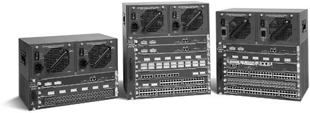
Figure 3-10 shows the 4503, 4506, and 4507R chassis in the Catalyst 4500 series product line.
Figure 3-10. Catalyst 4500 Series Switches
Supervisors and Switch Fabrics
The Catalyst 4500 series switches support five different Supervisor modules. With the Catalyst 4500 series, the capacity of the switch fabric is determined by the Supervisor installed. Unlike other Catalyst platforms such as the Catalyst 6500 that use per port buffers and are capable of distributing forwarding intelligence to the line modules, all forwarding decisions and packet buffering are handled by the Supervisor. The five Catalyst 4500 Supervisor modules are
Supervisor II? The Supervisor II enables a 64-Gbps switch fabric when installed in a 6-slot chassis, and is capable of handling only Layer 2 forwarding decisions. Using 64-byte packets, the Supervisor II can process a maximum of 18 million packets at Layer 2. All packets are processed by the supervisor and buffered using 8 MB of shared packet buffers. The Supervisor II includes two Gigabit Ethernet uplink ports using GBIC connectors.
The Supervisor II supports an optional Layer 3 services module (WS-X4232-L3) that is capable of processing around 6 Mpps at Layer 3. The Supervisor II utilizes three central forwarding ASICs that Cisco has dubbed the "K1," named after the "Kirky Architectural Specification." Each of the three K1 ASICs supports twelve 1-Gbps full-duplex connections for a total of 24 Gbps (full duplex) per ASIC. Each of the three K1 ASICs are responsible for handling one third of the ports on each line card, and are interconnected via 1-Gbps links. Because of these 1-Gbps interconnections, a bottleneck is created when traffic needs to move from ports serviced by one K1 to ports serviced by another K1 on the supervisor.
Supervisor III? The Supervisor III enables a 64-Gbps switch fabric when installed in a 6-slot chassis, and uses the next generation K2 ASIC capable of Layer 2, Layer 3, and Layer 4 packet processing. The Supervisor III is capable of advanced Layer 3 features including OSPF, EIGRP, and BGP. The K2 ASIC utilizes an entirely different architecture from the K1 by dividing packet handling functions into packet processing and fast forwarding. The packet processing engine (PPE) is responsible for receiving, storing, and transmitting all packets. The fast forwarding engine (FFE) is responsible for performing Layer 2, Layer 3, and Layer 4 lookups and processing ACLs and QoS decisions. Because only one K2 ASIC is used, the Supervisor III does not suffer from the same performance limitations as the Supervisor II.
Supervisor II+? The Supervisor II+ enables a 64-Gbps switch fabric when installed in a 6-slot chassis, and uses the same K2 ASIC as the Supervisor III and IV. The Supervisor II+ is capable of Layer 2, Layer 3, and Layer 4 packet processing like the Supervisor III and IV, but is capable of only basic Layer 3 features such as RIPv1/v2. Because the Supervisor II+ cannot run OSFP, EIGRP, and BGP, it is positioned by Cisco as a wiring closet solution. The Supervisor II+ can provide redundancy when two are installed in the Catalyst 4507R.
Supervisor IV? The Supervisor IV enables a 64-Gbps switch fabric when installed in a 6-slot chassis, and uses the same K2 ASIC as the Supervisor II+ and III. The Supervisor also offers redundancy by implementing dual Supervisors in the Catalyst 4507R. In addition to Supervisor redundancy, the Supervisor IV offers NetFlow support via an optional daughterboard. The Supervisor IV supports the enhanced Layer 3 routing features as the Supervisor III.
Supervisor V? The Supervisor V enables a 96-Gbps switch fabric when installed in a 10-slot chassis, and uses the same K2 ASIC as the Supervisor II+, III, and IV. The Supervisor V provides improved support for as many as 48 wire-speed Gigabit Ethernet ports and is backward compatible with the Catalyst 4006 and all Catalyst 4500 series chassis. The 4510 chassis requires a Supervisor V for operation, and when installed in redundant mode, all four Gigabit Ethernet uplinks are active.
Figure 3-11 shows the Supervisor V for the Catalyst 4500 series switches.
Figure 3-11. Supervisor V for Catalyst 4500 Series
Line Modules
A wide variety of line modules are available for the Catalyst 4500 platform because legacy Catalyst 4000 line modules are compatible with the 4500 series platforms. The Catalyst 4500 supports various densities of 10/100 and Gigabit Ethernet, with future support planned for 10 Gigabit Ethernet.
Catalyst 4000/4500 series line cards are considered to be functionally transparent, meaning they do not contain local packet forwarding or processing capabilities, and are essentially only interfaces to the ASICs on the Supervisors. This is in contrast to the local forwarding and buffering capabilities of Catalyst 6500 line modules.
Each Catalyst 4000/4500 line module uses what is called stub ASICs. The stub ASICs have the simple responsibility of splitting the six 1-Gbps connections from the Supervisor into the proper speed and bandwidth for each port on the line module.
A complete list of available line cards for the Catalyst 4500 can be found by searching the Cisco Systems website at Cisco.com.
Power and Cooling
The Cisco Catalyst 4500 Series internal power supplies are available in four power ratings:
1000W AC input (data only)
1300W AC input (data and in-line power)
1400W DC input (data and in-line power)
2800W AC input (data and in-line power)
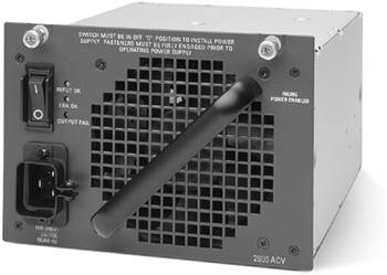
Figure 3-12 shows an example of the 2800W AC power supply for the Catalyst 4500 series switches.
Figure 3-12. Catalyst 4500 Power Supplies
The Catalyst 4500 series power supplies differ from other Catalyst platforms by coupling what are essentially two power systems into one power supply. The 1300W and 2800W power supplies divide their total power capabilities between data and in-line power for devices such as IP phones or wireless access points. Each Catalyst 4500 chassis supports up to two power supplies running in either redundant or combined power mode:
Redundant mode? In redundant mode, both power supplies are on line, with each power supply providing half the power to the system. In this mode, the switch manages power so that should one power supply fail completely, the other is providing enough power for the system to continue uninterrupted operation. In this mode, total power to the system does not exceed the capabilities of one power supply.
Combined mode? In combined mode, the Supervisor combines the power from both power supplies to provide more power than is available from a single power supply. In combined mode, a single power supply failure could cause interruption of power to some in-line powered devices if the total power used by the system exceeds the capabilities of a single power supply.
Power supplies installed in pairs must be identical types when the system is powered on, but individual power supplies can be upgraded but not downgraded during switch operation. A system error message will be reported when upgrading power supplies during live operation. Some configurations of line modules and in-line powered devices may exceed the capabilities of the internal power supplies. In these situations, as many as two external 220VAC power shelves can be added to provide additional power.
Unlike the Catalyst 6500 series, the Catalyst 4500 series only supports one type of internal fan tray. Each fan in the tray is independent and the system can cool properly with only one fan operating. Should a fan fail, an error message is generated to inform the user of the failure.
Data Flow on the Catalyst 4500
Figure 3-13 illustrates at a high level the transmission of a unicast packet from Host1 connected to a Gigabit port on Module 3 to Host2 connected to a 10/100/1000 port on Module 4. Again, only key ASICs are listed on the supervisor and line modules; their locations are not necessarily "anatomically correct."
Figure 3-13. Data Flow on the Catalyst 4500
The WS-X4306-GB six-port Gigabit line module is used in Slot 3 and the WS-X4448-GB-RJ 48-port 10/100/1000 line module is used in Slot 4. Because the K1 architecture is not being carried forward into new Catalyst 4500 series products, the data flow example demonstrates the K2 architecture of the Supervisor II+, III, and IV. The data flow example assumes hardware switched packets.
The following explanation corresponds to the data flow shown in Figure 3-13:
Host1 transmits a packet. Packet is received by Module 3 and transmitted onto the backplane to the Supervisor.
The packet is stored in buffer memory (256-byte buffers) and the PPE builds a lookup descriptor for the FFE.
The lookup descriptor is sent to the FFE. The FFE performs Layer 2 and Layer 3 lookups along with any ACL or QoS processing.
A packet transmit descriptor is created by the FFE as a result of the lookups and sent back to the PPE.
The PPE rewrites the packet and transmits it to Module 4.
The stub ASIC on Module 4 utilizes round-robin scheduling to determine when to transmit the packet.
The packet is transmitted to Host2.


