In the Beginning-Catalyst 5000/5500 (Project Synergy)
The origins of Cisco's best-selling LAN switching products took shape in 1994 as a project code named Synergy. The goal of project Synergy was to provide dedicated switching (with optional multilayer switching and routing) for 10 and 100 Mbps Ethernet and Token Ring workgroups to Fiber Distributed Data Interface (FDDI), 100 Mbps Ethernet, and Asynchronous Transfer Mode (ATM) backbones. The network world has come to recognize the results of project Synergy as the Catalyst 5000 switch.
The Catalyst 5000 switch introduced a five-slot chassis with one slot reserved for a supervisor module, hot swappable line modules, redundant power supplies, redundant fans, and a 1.2-Gbps backplane bus.
Since the introduction of the original Catalyst 5000 and resulting line of Catalyst switches, Cisco developed substantial improvements in switching architecture, all geared toward processing ever-increasing amounts of traffic. In addition to increased traffic-processing capabilities, switches are now able to make more intelligent traffic forwarding decisions using information found at OSI Layer 3 (Network) and Layer 4 (Transport).
A short time after the introduction of the Catalyst 5000 switch, Cisco introduced additional models including the Catalyst 5500 series. Catalyst 5500 series switches offer an aggregate switching bandwidth of 3.6 Gbps by implementing three individual 1.2-Gbps buses.
Catalyst 5000/5500 Switch Components
Every Catalyst switch is made up of essentially the same general components:
Chassis
Power and cooling
Supervisor module(s)
Line module(s)
Most Catalyst switches are modular and allow user replacement of each component listed previously, but some are fixed in configuration. Nonetheless, even fixed configuration switches contain the same basic functionality.
In the next section, the Catalyst 5000/5500 family of switches is used to examine the common components of a switch.
Chassis
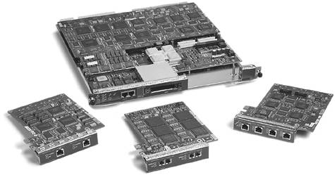
The switch chassis is the physical housing for all switching modules, power supplies, and cooling equipment. The chassis provides the electrical connections between the Supervisor module and all other modules or line cards as well as the system clock, which is used for bus timing, and connections to the power supplies. After a supervisor module and line modules are inserted into a chassis, the communication paths are enabled. Figure 3-1 is an example of a fully populated Catalyst 5000 switch.
Figure 3-1. Fully Populated Catalyst 5000 Switch

Following the introduction of the Catalyst 5000, four additional Catalyst 5000 and 5500 series chassis were introduced, as described in Table 3-1.
Model | Description |
|---|---|
5000 | Catalyst 5000 Series 5-slot chassis |
5002 | Catalyst 5000 Series 2-slot chassis |
5505 | Catalyst 5500 Series 5-slot chassis |
5509 | Catalyst 5500 Series 9-slot chassis |
5500 | Catalyst 5500 Series 13-slot chassis |
Power and Cooling
Every switch will have one or more power supplies and fans for power and cooling. All but the least expensive Catalyst switches, fixed configuration or modular, offer some type of power supply redundancy.
The original Catalyst 5000 has two power supply bays and supports load sharing between the two power supplies when both are installed. If only one power supply is powered-on on the Catalyst 5000, the system status LED on the Supervisor will glow red instead of green. Over the years, customers have opened numerous trouble tickets to determine why the system status LED on their Supervisor was red when the root cause was simply a single active power supply. A complete list of supervisor system LED statuses is available in the Catalyst 5000/5500 series documentation at cisco.com.
Supervisor Module
The Supervisor module contains the "brains" of the switch. The Catalyst 5000 introduced a Supervisor I containing a number of subcomponents including the following:
Network Management Processor (NMP)? The NMP handles administrative functions such as calculating spanning tree(s), virtual terminal sessions, Simple Network Management Protocol (SNMP), and synchronization of secondary supervisor modules.
Master Communications Processor (MCP)? The MCP communicates statistical and Remote Monitoring (RMON) information to and from the Local Communications Processor (LCP) on each line module via the Serial Communications Protocol (SCP).
Nonvolatile random-access memory (NVRAM)? NVRAM is used to store the configuration of the switch.
Dynamic random-access memory (DRAM)? DRAM is used as working memory by the operating system.
Flash memory? Flash memory is used to store the switch operating system and can be used to store backup configurations.
Content-Addressable Memory (CAM)? CAM is used to store the table of learned MAC addresses, port, and VLAN information; commonly referred to as the CAM table.
In addition, the Supervisor I contains highly specialized application-specific integrated circuits (ASICs) including the following:
Enhanced Address Recognition Logic Version (EARL)? The EARL ASIC creates and updates the table of MAC addresses to port mappings stored in CAM.
Synergy Advanced Interface Network Termination (SAINT)? The SAINT ASIC provides the 10/100 Mb Ethernet controller powering the Supervisor's Ethernet uplink ports. The Supervisor utilizes one SAINT ASIC per uplink port.
Synergy Advanced Multipurpose Bus Arbiter (SAMBA)? The SAMBA ASIC handles central arbitration and access to the data bus.
NOTE
It is important to understand the version and functionality of the EARL ASIC on each Supervisor. As newer Catalyst switches were introduced, the EARL evolved with new capabilities, and is commonly referred to in architectural discussions. Documentation of Catalyst switching architecture and Supervisors often includes references to the version of EARL implemented. Understanding the different versions of EARLs can help quickly determine the forward intelligence of a supervisor module. The next section of this chapter describes EARL functionality in detail.
Figure 3-2 is a picture of the original Supervisor I for the Catalyst 5000 series switch.
Figure 3-2. Catalyst 5000 Supervisor I Module
Since the introduction of the Catalyst 5000 series and the Supervisor I, four additional Supervisor modules have been introduced. A description of each supervisor and its capabilities follows:
Supervisor I? The Supervisor I is capable of Layer 2 switching only and is not upgradable to Multilayer Switching (MLS). Chapter 6, "Understanding Multilayer Switching," describes MLS in detail. The Supervisor I does not support any redundancy using a second standby supervisor and is not compatible with the 5500 series. The Supervisor I includes two Fast Ethernet uplink ports with a variety of support for different media types.
Supervisor II? The Supervisor II is also a Layer 2-only switching engine and introduces support for redundancy with an optional second supervisor. The Supervisor II also includes two Fast Ethernet uplink ports with a variety of support for different media types.
Supervisor IIG? The Supervisor IIG includes an integrated NetFlow Feature Card (NFFC) and supports the addition of an optional Route Switch Feature Card (RSFC). The RSFC is essentially an NPE-200 (see the 7200 Router Platform at www.cisco.com) on a daughterboard. A Supervisor IIG with its built-in NFFC and optional RSFC card enables MLS. In addition, the "G" in the Supervisor IIG signifies support for modular Fast Ethernet and Gigabit Ethernet uplink ports.
Supervisor III? The Supervisor III includes support for an integrated NFFC but does not support the addition of an RSFC. When installed in a Catalyst 5500 series switch, the Supervisor III enables the 3.6-Gbps crossbar switch fabric. The Supervisor III also includes support for modular Gigabit Ethernet uplink ports similar in configuration to the now standard Gigabit Interface Connector (GBIC).
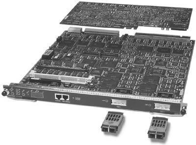
Supervisor IIIG? The Supervisor IIIG includes an integrated NFFC and supports the addition of an RSFC. When installed in a Catalyst 5500 series switch, the Supervisor IIIG enables the 3.6-Gbps crossbar switch fabric and includes support for standard GBIC uplink modules. Figure 3-3 is an example of the Supervisor IIIG module.
Figure 3-3. Catalyst 5xxx Supervisor IIIG Module
EARL Functionality
The Catalyst 5000 EARL is a single ASIC integrated into the Supervisor itself, but later platforms such as the 6500 use multiple ASICs on daughterboards to provide EARL functionality, each responsible for a specific task such as Layer 3 lookup, access control list (ACL) matching, or quality of service (QoS). As platforms have evolved, many versions of the EARL have been introduced. These are discussed in more detail later in this section.
As mentioned in the previous section, the EARL creates and maintains the forwarding tables stored in CAM. The EARL also conducts the lookup operations for each frame received by the switch and determines which ports should forward and which should discard or flush. In its most basic form, the EARL ASIC(s) accomplishes this task by examining the header information from each frame to determine if an entry already exists in the CAM table for the destination address of the frame. If an entry exists, the EARL rewrites the frame and sends it to the line modules, which contain ports that must forward the frame.
EARL version 1 on the Catalyst 5000 created forwarding tables that consisted of the MAC address of individual network devices, the VLAN ID associated with each MAC address, and an index value. The VLAN ID is a 16-bit field, 10 of which are used today. Using 10 bits, the Catalyst 5000 supports up to 1024 individual virtual LANs (VLANs). Additional bits in the EARL tables include the following:
An aging bit? The aging bit is used for aging addresses.
A trap bit? The trap bit is used to indicate an exception, typically that an address should be blocked or filtered.
A static bit? The static bit is used to support static or manually entered addresses.
A valid bit? The valid bit is used so that aged-out addresses are not used.
With the introduction of the EARL2 on the NFFC, the supervisor is capable of examining and acting on Layer 3 IP packet information. After an initial routing decision is made by either an internal (RSM or RSFC) or external router, the EARL2 can rewrite subsequent similar packets based on that information, without sending the packet to the route processor for a routing decision.
In addition, some newer line modules on the Catalyst 5500 are equipped with specialized ASICs capable of what is termed in-line rewrite, allowing them to rewrite Layer 3 based on information provided by the EARL. Line modules capable of in-line rewrites are able to rewrite Layer 3 without the help of the supervisor.
Because the EARL is responsible for creating and maintaining the CAM table, all forwarding stops anytime a Supervisor is reset or removed. In switches that support redundancy using dual supervisors, high-availability software features synchronize one or more forwarding tables between the EARLs on each Supervisor, allowing forwarding to continue after a brief, or sometimes not so brief, pause, depending on the platform. Chapter 11, "Design and Implementation Best Practices," discusses high availability using redundant supervisor on various platforms in detail.
CAM and TCAM
The terms CAM and ternary CAM (TCAM) have become almost interchangable with today's switches because all the switching architectures discussed in this chapter are capable of making switching decisions using Layer 3 and Layer 4 information, along with ACLs and QoS parameters. As described earlier in the section "Supervisor Module," a CAM stores the table of learned MAC addresses, ports, and VLAN information. This information is found at Layer 2 and is the basic information every switch needs to function.
The TCAM gets its name from the system of storing 0s, 1s, and *s (* = Don't Care) used to match patterns of entries in the tables. Because this CAM stores three values, the term ternary (meaning having three elements) describes this type of CAM. Depending on the platform, various ASICs program and process TCAM entries for functions such as ACLs and QoS in hardware. Both the CAM and TCAM information is processed in parallel during a lookup, resulting in wire-speed processing of packets by the switch.
Catalyst 5000/5500 EARL Versions
Knowing the version of EARL in use helps determine the forwarding intelligence of each platform. Table 3-2 shows existing EARL versions and their forwarding capabilities.
Supervisor Part Number | Supervisor Model | EARL Version Subtype |
|---|---|---|
WS-X5005 | Supervisor I | EARL1 |
WS-X5006 | Supervisor I | EARL1 |
WS-X5009 | Supervisor I | EARL1 |
WS-X5505 | Supervisor II | EARL1+ |
WS-X5506 | Supervisor II | EARL1+ |
WS-X5509 | Supervisor II | EARL1+ |
WS-X5530-E1 | Supervisor III | EARL1++ |
WS-X5530-E2 | Supervisor III NFFC | EARL2 (NFFC) |
WS-X5530-E2A | Supervisor III NFFC-A | EARL2 (NFFC) |
WS-X5530-E3 | Supervisor III NFFC II | EARL3 (NFFC II) |
WS-X5530-E3A | Supervisor III NFFC II-A | EARL3 (NFFC II) |
WS-X5534 | Supervisor III F | EARL1++ |
WS-X5540 | Supervisor II G | EARL 3 (NFFC II) |
WS-X5550 | Supervisor III G | EARL3 (NFFC II) |
Switch Bandwidth
Switch bandwidth can be calculated by multiplying the width of the data bus times the clock speed. In project Synergy, each Catalyst 5000 data bus is 48 bits wide and operates at a speed of 25 MHz. The resulting calculation (48 * 25,000,000) = 1,200,000,000 or 1.2 Gigabits per second (Gbps).
With faster processors, greatly improved switch fabrics, and distributed forwarding capabilities, newer Catalyst platforms such as the Catalyst 3750, 4500, and 6500 can achieve data transfer ranging from 32 Gbps to 720 Gbps.
In addition to raw bandwidth, a commonly advertised performance number is the maximum packets per second that can be forwarded by the central switch processors. For example, the Catalyst 6000 with a Supervisor I advertises 32 Gbps of switch bandwidth and is capable of forwarding 15 million packets per second (Mpps).
Line Modules
The first Ethernet line modules introduced along with project Synergy (Catalyst 5000) included the following:
12-port, 10/100 Mbps autonegotiation Ethernet/Fast Ethernet with RJ-45 connectors for unshielded twisted-pair (UTP) Category 5 cable
24-port, 10 Mbps Ethernet with two RJ-21 Amphenol connectors
12-port, 10 Mbps 10BASE-FL with ST fiber connectors
48-port, 10 Mbps group switched Ethernet with four RJ-21 Amphenol connectors (4 switched ports, 12 shared ports per switched port)
12-port, 100 Mbps 100BASE-FX with SC fiber connectors
24-port, 100 Mbps Fast Ethernet with RJ-45 connectors for UTP Category 5 cable (3 switched ports, 8 shared ports per switched port)
24-port, 10 Mbps Ethernet with RJ-45 connectors for UTP Category 5 cable
These first modules were limited to 10 and 100 Mbps Ethernet, and introduced many years prior to Gigabit Ethernet becoming a standard.
Each Ethernet line module consists of specialized ASICs providing the module's forwarding capabilities. In the case of the 12-port, 10/100 Mbps Ethernet/Fast Ethernet module, one SAINT ASIC is required for each 10/100 Mbps port on the module.
Since the introduction of the Catalyst 5000, many additional line modules or modules have been introduced. A complete list can be obtained at the Cisco Systems website at Cisco.com. Figure 3-4 shows one of the first 10/100 Ethernet Switching modules.
Figure 3-4. Catalyst 5xxx 16 Port 10/100 Ethernet Switching Module

Catalyst 5000/5500 Architectures
As previously discussed in this chapter, the Catalyst 5000 line of switches uses a shared bus architecture to transport incoming frames from source to destination. The Catalyst 5000 uses a total of three buses to move data, communicate configuration and network management information, and determine which ports should forward or discard frames.
The following describes the bus types on the Catalyst 5000 series:
Switching or data bus (dBus)? The dBus is used to switch frames between line cards. The data bus is 48 bits wide and operates at 25 MHz, yielding 1.2 Gbps of bus bandwidth.
Management bus (mBus)? The mBus carries configuration information from the NMP to each module and statistical information from each module to the NMP, using the Serial Communication Protocol (SCP).
Results/index bus (rBus)? The rBus carries port-select information from the central EARL ASIC to the ports. This information determines which ports forward the packet and which flush it from the buffer.
The Catalyst 5500 series implements these same three buses, plus two additional data buses, each providing 1.2 Gbps of bandwidth, yielding 3.6 Gbps of total bus bandwidth. To maintain backward compatibility with the Catalyst 5000 line cards, the chassis of the 5500 series were designed so that newer line cards connected to all three buses, while still allowing older Catalyst 5000 line cards to connect to a single bus. Figure 3-5 illustrates the types of the connections on the Catalyst 5500 backplane.
Figure 3-5. Catalyst 5500 Backplane Connections
The Catalyst 5500 introduced a 5-Gbps Asynchronous Transfer Mode (ATM) cell switch bus for use with an optional ATM switch processor based on Cisco Lightstream 1010 technology. As with all Catalyst switches, Slot 1 is reserved for a Supervisor module. Switching modules installed in Slots 1?5 connect to all three 1.2-Gbps buses providing 3.6 Gbps of total bandwidth.
While Gigabit Ethernet modules are available for the Catalyst 5000 and 5500 series, certain restrictions apply to where they can be installed to provide enough bandwidth to enable all the ports. Gigabit Ethernet modules should be installed in slots with connections to all three 1.2-Gbps buses. Slot 13 is reserved for the ATM switch processor (ASP). A detailed discussion of the ATM switching capabilities on the Catalyst 5500 is beyond the scope of this book. More information on Catalyst 5500 ATM switching capabilities is available on the Cisco website at Cisco.com.
Data Flow on the Catalyst 5000
Figure 3-6 describes the path a frame takes from the time it is received on an input port on the WS-X5224, to the time it is transmitted out the egress port on another WS-X5224, using the central rewrite function on the EARL on the Supervisor. This is a high-level overview, focusing on the major steps of forwarding a frame.
Figure 3-6. Data Flow on the Catalyst 5000
The following list corresponds to the process illustrated in Figure 3-6:
Host A transmits an Ethernet frame destined for Host B. When the frame arrives on an input or ingress port on Slot 2, it is fully stored in input buffers and a Frame Check Sequence (FCS) is run on the frame to determine if the frame is "good." If the frame passes the FCS, a 15-byte header is added to the frame containing the port number and VLAN.
The ingress port then requests access to the data bus through the local arbiter on the line card.
The line card's local arbiter then requests access to the data bus through the central arbiter (SAMBA).
After the line card's local arbiter is granted access to the switching bus by the central arbiter on the Supervisor, the frame is transmitted onto the switching bus where all line cards receive it, including the Supervisor.
Because the EARL is on the Supervisor, it gets a copy of the frame and goes to work. The EARL inspects the destination address, source address, and VLAN ID of the packet. The MAC address and VLAN ID are then put through a hash function, resulting in a 15-bit address. This 15-bit address gets compared to the forwarding information in the CAM table. When the 15-bit hash matches an existing entry in the CAM table, the EARL uses what is called Local Target Logic (LTL) and Color Blocking Logic (CBL) to determine which line cards should forward the frame. VLAN numbers were originally referred to by "colors" as an easy way to identify different VLANs.
The resulting information is sent via the rBus to each line card.
LTL on each line card then determines which ports are to forward the frame. The Ethernet port connected to Host B on Slot 3 transmits the frame to Host B. All other ports on all other line cards simply discard the frame.
If a frame has a broadcast address or does not match an existing entry in the CAM table, the MAC address along with the VLAN ID are sent on the rBus to flood out all ports that belong to that VLAN, excluding the port on which the frame was received.


