MLS on Catalyst 6500
Supervisor 1 with MSFC1/2 with PFC 1 can do MLS internally. MLS on the Catalyst 6500 is enabled by default. No configuration changes are necessary on MSFC or the Catalyst switch. The communication between MSFC and PFC is done via Serial Communication Protocol (SCP). PFC handles all the shortcuts created. It can store up to 128 K entries, but typically, the range is in the 30?40 K entries. If many entries are in the MLS table, the timers can be tuned to flush some of the older entries from the table. Naturally, this puts more stress on the switch because it has to repopulate the table periodically. Using the Fast Aging Timer feature, set mls agingtime fast, allows for a more manageable MLS table. To disable MLS for a VLAN, use the no mls ip on the desired interface. This is generally done for debugging purposes.
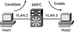
The rewrite function is the same as a Catalyst 5000 switch. The PFC changes the MAC destination address to point toward Host2 rather than the MSFC (see Figure 6-6). It also changes the source MAC address from Host1 to the MSFC MAC address. The PFC decrements the TTL and does a Layer 3 checksum on the packet. Layer 3 information remains the same. The result is the packet is now Layer 3 switched by the PFC.
Figure 6-6. Catalyst 6500 with MSFC

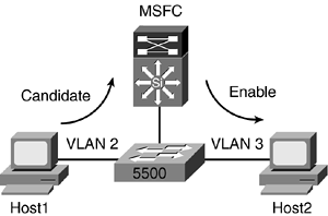
In this environment, the MSFC is performing the MLS-RP for the Catalyst 5500 that is connected to the Catalyst 6500 switch. The Catalyst 5500 will be able to create the Layer 3 shortcut between Host1 and Host2 (see Figure 6-7).
Figure 6-7. Catalyst 6500 with MSFC as the RP for Catalyst 5500

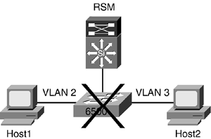
The PFC off the Catalyst 6500 will not perform MLS-SE in a Catalyst 5500, as shown in Figure 6-8. The Layer 3 shortcut does not occur in the Catalyst 6500. It does, however, occur on the Catalyst 5500 that houses the RSM.
Figure 6-8. PFC Does Not Act as MLS-SE for Catalyst 5500 Switches

The following process is illustrated using a Supervisor 1A with PFC1 as the packet enters a Catalyst 6500 ingress port, shown in Figure 6-9:
Host1 sends traffic to Host2 that resides on a separate VLAN.
The packet arrives at the ingress port. The switch stores the packet in the Pinnacle ASIC and does a FCS check on the packet. If the FCS check is bad, it will drop the packet. Assuming the packet is good, the Pinnacle requests access to the data bus (dBUS) from the Local Arbitrator. The port adds 256-bit dBus header. The header contains sequence number, source port, index, VLAN, and so on.
The Central Arbitrator provides Local Arbitrator on the module access to the dBus in a round-robin fashion.
The packet is forwarded to all other ports. PFC1 has four main engines:
- Layer 2 Forwarding engine
- Layer 3 Forwarding engine
- Access List engine
- Multicast Replication engine
These engines also have an interface to the dBus and will receive the traffic that was generated by the ingress port. The packet lookups by these engines happen simultaneously.
The Layer 2 engine does a lookup in the Layer 2 forwarding table for the 6-byte destination MAC address. If the destination is the router MAC, the Layer 2 engine will signal the Layer 3 engine to take over. This is the first Layer 2 lookup. The Layer 2 engine may require a second lookup depending on what happens on the other engines.
While Layer 2 is examining the packet, Layer 3 also does a lookup on the packet to see if it has a NetFlow table for the destination.
The ACL engine checks to see if there is an inbound/outbound access list defined for the port. It will forward this information to the Layer 3 engine.
The Layer 3 engine with its interaction with the Layer 2 engine will have the rewrite information for the flow. If there is no entry in the NetFlow table, the Layer 2 engine will create a Candidate entry and send the traffic toward the MSFC.
The rewrite information will be sent via the results bus (rBus) to the destination port for rewrite by the router.
The Layer 3 engine forwards Layer 3 rewrite information along with the ACL information to the Layer 2 engine for future use.
Layer 2 does a second lookup for the final destination, Host2. The Layer 2 engine must know the MAC address of Host2, or otherwise, the Enable entry will not take place.
Any subsequent packets will be hardware switched.
Figure 6-9. Catalyst 6500 with MSFC

Again, no configuration changes are needed to enable MLS on a Catalyst 6500 switch with Supervisor 1A. To check the status of MLS on the MSFC, use the show mls status command. The show mls rp command is only relevant to MSFC acting as an RP for an external Catalyst 5000 family.
Example 6-9 shows an MLS table for the Catalyst 6500 switch.
Example 6-9. MLS Table
Switch2 (enable) show mls entry

Destination-IP  Source-IP       Prot  DstPrt SrcPrt Destination-Mac   Vlan EDst

ESrc DPort     SPort     Stat-Pkts  Stat-Bytes  Uptime   Age

--------------- --------------- ----- ------ ------ ----------------- ---- ----

---- --------- --------- ---------- ----------- -------- --------

MSFC 10.1.30.20 (Module 15):

10.1.3.3        10.1.34.4       ICMP  0      0      00-05-74-18-04-bc 30   ARPA

ARPA 1/1       3/2       4          400         00:00:35 00:00:35

10.1.34.4       10.1.3.3        ICMP  0      0      00-04-c1-5f-78-81 34   ARPA

ARPA 3/2       1/1       4          400         00:00:35 00:00:35
In Example 6-10, the rlog command provides information about whether the PFC is getting traffic from MSFC or not. This can be useful in troubleshooting MLS issues. The output in Example 6-10 shows the MSFC and PFC are communicating because the router port is added to the MLS table with its associated XTAG value.
Example 6-10. rlog Output
Switch2 (enable) show mls rlog l2

SWLOG at 81f53810: magic 1008, size 51200, cur 81f55c14, end 81f60020

Current time is: 09/23/03,16:21:42

538 09/22/03,17:51:16:(RouterConfig)Router_Cfg(2793): ClearL3Entries xtag 1, vla

n 25

537 09/22/03,17:51:16:(RouterConfig)Router_cfg: router_add_mac_to_earl 00-30-b6-

3e-53-c4  added for mod 15/1 Vlan 25 Earl AL =0

536 09/22/03,17:51:16:(RouterConfig)Router_Cfg: Process add mls entry for mod 15

/1 vlan 25 i/f 1, proto 0, LC 0

535 09/22/03,17:51:16:(RouterConfig)Router_Cfg(2793): ClearL3Entries xtag 1, vla

n 25


