Trunking Methods
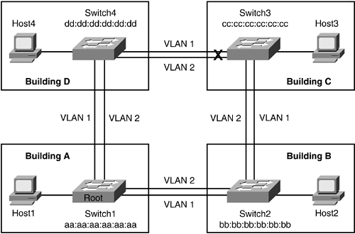
The examples so far in this chapter demonstrate one VLAN spanning multiple switches. In the real world, typically, a great number of VLANs are configured, which are extended to multiple switches. Figure 4-3 shows two VLANs in the switched network. Each VLAN has its own STP-topology, IP range, and network requirements.
Figure 4-3. Multiple Switches with Two VLANs

Now imagine a third VLAN is added, which requires another physical link between the switches. Because it may not be efficient to continue to add links as the number of VLANs grows, the solution is trunking. A trunk can be configured between two or more switches, between a router and a switch, or between a switch and a host such as a server. Check the hardware to find out what type of trunking capabilities a device has, if any. This section will primarily concentrate on trunking between Cisco switches.
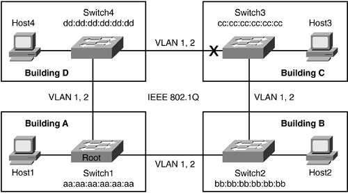
A trunk multiplexes multiple VLANs over a single physical connection. This kind of multiplexing is conceptually similar to the way many television signals are multiplexed onto the airwaves using different frequencies. In this analogy, each VLAN acts like a different television station, while sharing the same physical wire.
Cisco supports only two types of trunks using Fast, Gigabit, and 10 Gigabit Ethernet ports: Cisco Inter-Switch Link Protocol (ISL) and IEEE 802.1Q. The Dynamic Trunking Protocol (DTP) allows a port to negotiate which method to use for trunking. DTP will first attempt to form an ISL trunk if both switches support it; if not, DTP will attempt IEEE 802.1Q. DTP uses the address 01-00-0C-CC-CC-CC with a SNAP value of 0x2004. DTP sends messages every 1 second, and after formation of the trunk, every 30 seconds. The ports negotiating the trunk will not participate in spanning tree until the negotiation is complete. Recently, IEEE 802.1Q is being implemented in networks because it is an IEEE standard, whereas ISL is proprietary to Cisco. Many Cisco routers and some older Cisco Catalyst switches do not support dynamic trunking. In these cases, a static configuration is required. Figure 4-4 shows two VLANs 1 and 2 running over the same cable because of the use of trunking, whereas before, an extra connection was required between the switches in the diagram as depicted in Figure 4-3.
Figure 4-4. Trunks Used Between Switches

Trunking is an integral part of networking, and it is worth going over Cisco ISL and IEEE 802.1Q methods in detail. This section will also provide some best practices that will help with properly configuring the switches.
Inter-Switch Link Protocol
ISL encapsulates the Ethernet frame with a 26-byte header and a 4-byte frame check sequence (FCS) for a total of 30 bytes of overhead. ISL requires a minimum Fast Ethernet connection between the two devices. The 15-bit VLAN field in the ISL header allows for the multiplexing of the VLANs on a single wire. ISL supports up to 1024 VLANs because Cisco switches use the lower 10 bits of the 15-bit field. The range of ISL packet sizes is 94 bytes (64-byte minimum Ethernet frame + 30-byte ISL overhead) to 1548 bytes (1518-byte maximum Ethernet frame + 30-byte ISL overhead). Each VLAN will have its own spanning-tree topology in an ISL trunking configuration. For instance, if there are two VLANS configured on an ISL trunk, each VLAN will have its own root and spanning-tree topology layout.
The following describes the fields of the ISL encapsulation frame shown in Figure 4-5:
DA? The destination address uses the multicast MAC address 01-00-0C-00-00-00.
Type? The type of frame encapsulated: Ethernet (0000), Token Ring (0001), FDDI (0010), and ATM (0011).
User? This field is used as an extension for the technologies covered under the Type field. The User field can also be used to define priority of the frame. The default value is 0000 for Ethernet with low-priority traffic.
SA? Source address of the switch transmitting the ISL frame.
Len? The length of the packet.
AAAA03? Standard SNAP 802.2 LLC header. This value is constant.
HSA? High bits of SA.
VLAN? VLAN ID.
BPDU? STP bridge protocol data unit/Cisco Discovery Protocol (BPDU/CDP) for control traffic.
Index? The port index of the source of the packet.
Res? Reserved field for additional information, for instance, Token Ring or FDDI Frame Check Sequence field. For Ethernet, this field should be zero.
Encap Frame? The actual Ethernet frame.
ISL CRC? Four-byte check on the ISL packet to ensure it is not corrupted.
Figure 4-5. Frame Using ISL Encapsulation

IEEE 802.1Q
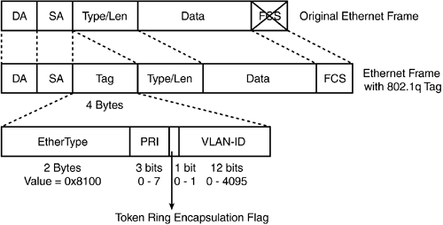
While ISL encapsulates an Ethernet frame with a 30-byte header, IEEE 802.1Q simply adds an additional 4-byte Tag field to the Ethernet frame (EtherType 0x8100). The Tag field has three components in addition to the EtherType:
Priority (3 bits)? The Priority field is used by 802.1p to implement Layer 2 quality of service (QoS).
Canonical Format Identifier (CFI) (1 bit)? The CFI bit is used for compatibility purposes between Ethernet and Token Ring.
VLAN ID (VID) (12 bits)? The VID field is used to distinguish between VLANs on the link.
FCS is recomputed after the 4-byte tag is inserted. IEEE 802.1Q supports up to 4096 VLANs because of the 12-bit length. The IEEE 802.1Q tag is not inserted on the native VLAN, which is the VLAN that the port was assigned to before becoming a trunk port. Figure 4-6 illustrates the IEEE 802.1Q tag format.
Figure 4-6. IEEE 802.1Q Tag Format

If the adjoining trunk port's native VLAN is different from the local port on the switch, a native mismatch VLAN error occurs. A mismatched native VLAN scenario will bridge VLAN STP information, which translates to having one single STP rather than STP for each VLAN defined. Example 4-1 shows an asterisk on the remote switch's port 1/1, which has a different native VLAN.
Example 4-1. Detecting a Native VLAN Mismatch
%CDP-4-NVLANMISMATCH:Native vlan mismatch detected on port 1/2

Switch1 (enable) show cdp neighbor

* - indicates vlan mismatch.

# - indicates duplex mismatch.

Port     Device-ID                       Port-ID                   Platform

-------- ------------------------------- ------------------------- ------------

 1/2     Switch#2                        1/1*                      WS-C6506
Configuration Best Practices
Trunking has five modes in which it can operate:
On
Off
Desirable
Auto
Nonegotiate
In nonegotiate mode, the switch will form a trunk, but will not send DTP frames. The other end switch has to be in On or Nonegotiate mode for nonegotiate to work. Typically, this type of setup is used for connecting a third-party switch that does not support DTP. Table 4-2 provides the details on the various trunking modes.
Mode | Description |
|---|---|
On | Forces the port to become a trunk port and persuades the neighboring port to become a trunk port. The port becomes a trunk port even if the neighboring port does not agree to become a trunk. |
Off | Forces the port to become a non-trunk port and persuades the neighboring port to become a non-trunk port. The port becomes a non-trunk port even if the neighboring port does not agree to become a non-trunk port. |
Desirable | Causes the port to negotiate actively with the neighboring port to become a trunk link. |
Auto | Causes the port to become a trunk port if the neighboring port tries to negotiate a trunk link. |
Nonegotiate | Forces the port to become a trunk port but prevents it from sending DTP frames to its neighbor. |
Cisco recommends Desirable-Desirable mode for all trunk ports.


